How Should LSR Overmolded Copper Busbar Insulation Be Designed Around Bolted Connections?
Answer Excerpt
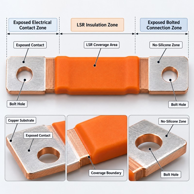
LSR overmolded copper busbar insulation should protect the intended conductor areas without covering the surfaces required for electrical connection, fastening or final assembly.
For copper busbars with bolted connections, the critical design decision is where the silicone insulation ends and the exposed metal connection area begins.
A reliable silicone over metal structure requires engineers to define:
• Insulated conductor sections
• Exposed electrical contact surfaces
• Bolt-hole locations
• Connection-pad dimensions
• Silicone coverage boundaries
• Metal insert positioning
• Metal surface and plating conditions
• Edge and bend geometry
• Assembly clearance
• Inspection and electrical validation requirements
The silicone should remain within the approved insulation zone and should not interfere with the intended metal-to-metal contact or mechanical clamping arrangement.
For high-voltage applications, the required insulation performance, electrical clearances and final assembly protection must be determined and validated against the customer's actual electrical specification.
Why Do Bolted Busbar Connections Need Separate Silicone Coverage Rules?
A copper busbar performs more than one function within an electrical assembly.
The main conductor section carries current between connection points. Local sections may connect to terminals, neighboring busbars, electrical equipment or mounting hardware.
For a bolted electrical joint, the mating metal surfaces must achieve the required contact condition after assembly.
Uncontrolled silicone coverage in this region may interfere with:
• Metal-to-metal contact
• Contact-pad seating
• Bolt installation
• Washer or fastener clearance
• Connection alignment
• Assembly inspection
• The specified joint clamping condition
Silicone accidentally trapped between conductive mating surfaces may prevent the intended contact arrangement from being achieved.
For this reason, the overmolding drawing should not simply indicate that the copper bar needs an insulating coating.
It should distinguish the insulated conductor section from the functional electrical joint.
The exposed joint may still require protection in the finished equipment. That protection must be addressed by the complete electrical assembly design rather than by allowing uncontrolled silicone into the bolted interface.
1. Define the Electrical Contact Zone and Silicone Termination Line
Before LSR injection molding, engineers should identify the exact boundaries of every area that must remain free from silicone.
For a typical copper busbar, these may include:
• Flat electrical connection pads
• Bolt holes
• Welding areas
• Terminal mating surfaces
• Threaded features, if present
• Precision locating surfaces
• Inspection datums
The 2D drawing should dimension the silicone termination line from a stable metal reference rather than from an approximate visual position.
Important drawing requirements include:
• Start and end of silicone coverage
• Minimum required exposed contact area
• Contact-pad clearance from silicone edges
• Bolt-hole clearance
• Permitted coverage variation
• Flash acceptance at the termination boundary
• Critical metal surfaces that must remain free from contamination
The purpose of these dimensions is to make the final overmolding result measurable.
A phrase such as “insulate the copper bar except for the ends” is not precise enough for a connection where the bolt position, contact area and assembly stack are controlled.
2. Keep Silicone Away From the Bolted Contact Interface
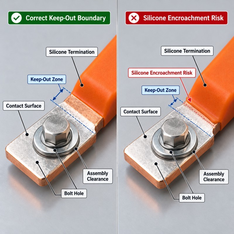
The end of the silicone layer should be positioned so that it does not enter the intended metal-to-metal contact area or interfere with the hardware envelope.
The required keep-out boundary depends on:
• Connection-pad geometry
• Bolt-hole position
• Washer dimensions
• Mating-busbar dimensions
• Assembly direction
• Contact-area specification
• Joint tolerances
• Access for inspection
Three different boundaries should be reviewed.
First, the electrical contact boundary defines where metal surfaces are intended to make electrical contact.
Second, the hardware clearance boundary defines the space needed for bolts, washers, tools and surrounding parts.
Third, the silicone coverage boundary defines where molded insulation ends.
These boundaries may be close together, but they should not be assumed to be identical.
Engineers should validate the actual assembled joint, including worst-case dimensional variation.
The finished overmolded busbar should allow the specified electrical connection to be assembled without cutting, scraping or manually removing silicone from a critical contact surface.
3. Control Busbar Flatness and Insert Position During LSR Molding
Copper busbars may be flat, bent, stepped or formed into customer-specific shapes.
The metal geometry affects how the insert is supported inside the mold.
If the busbar shifts or bends during molding, the silicone coverage may become inconsistent.
Potential results include:
• Uneven insulation thickness
• Shifted silicone termination lines
• Off-center coverage around bends
• Silicone flash near bolt holes
• Incorrect overall dimensions
• Assembly interference
• Changes in the final contact-pad position
The tooling should locate the copper insert from stable reference features.
Clamping or supporting features should not damage plated electrical contact surfaces or permanently deform the metal.
The incoming busbar tolerance should also be evaluated.
A metal insert that is already twisted or warped may create a variable cavity gap even when the mold itself is accurately manufactured.
During tooling trials, the metal insert dimensions should be checked before molding and the finished busbar dimensions should be checked again after silicone curing.
4. Review Copper Plating, Cleaning and Surface Condition
Copper busbars may be supplied with different surface finishes, coatings or plating depending on the electrical design.
The silicone contacts the actual surface condition presented to the mold.
For a controlled project, metal insert preparation should consider:
• Copper or copper-alloy grade
• Plating or coating type
• Stamping and bending residues
• Surface oxidation
• Handling contamination
• Cleaning requirements
• Burrs and sharp edges
• Packaging and storage conditions
A surface that performs well in an initial overmolding trial may behave differently when a different metal lot, surface treatment or cleaning process is introduced.
Where silicone adhesion is required, bonding feasibility should be verified on representative production inserts.
If primer or surface treatment is considered, it must be kept away from electrical contact surfaces unless the customer specifically approves its use.
The project should distinguish between surfaces intended for silicone adhesion and surfaces intended for electrical connection.
5. Design the Silicone Edge Around Bends and Thickness Transitions
Copper busbars are not always straight rectangular conductors.
They may contain bends, steps, changes in width or transitions between flat and raised sections.
These features affect how the silicone fills and how mechanical stress is transferred between the metal and elastomer.
Engineers should review:
• Bend radius
• Metal edge condition
• Silicone thickness at bends
• Coverage length
• Transition radius
• Potential peel-start locations
• Assembly movement
• Thermal expansion differences
• Demolding direction
Abrupt silicone termination at a sharp metal corner can concentrate stress at the interface.
An unsupported thin silicone edge may also become vulnerable to damage during handling or assembly.
Where possible, the design should provide a controlled edge transition that supports the intended insulation function without increasing the external dimensions unnecessarily.
However, adding grooves, holes or mechanical locking features should not be automatic.
Any change to the copper geometry must be approved against the customer's current-carrying, mechanical and electrical requirements.

6. Insulation Thickness Must Be Defined by Electrical Requirements
Silicone insulation thickness should not be selected only from a molding-process preference.
The required thickness depends on the electrical and environmental conditions of the finished application.
Relevant inputs may include:
• Operating voltage
• Required dielectric performance
• Insulation coordination requirements
• Conductor spacing
• Temperature range
• Mechanical contact risk
• Vibration exposure
• Contamination environment
• Required electrical testing
• Applicable customer or industry standards
A molded silicone layer may provide electrical insulation only when the material, geometry, manufacturing quality and test requirements are suitable for the project.
For that reason, engineers should avoid assigning a universal insulation thickness to every copper busbar.
The electrical design authority should establish the required performance, while the overmolding manufacturer evaluates whether the specified geometry and material can be manufactured consistently.
The finished insulated assembly must be validated before electrical safety or compliance claims are made.
| Design Item | Main Engineering Risk | What Must Be Defined |
Conductive contact pad | Silicone interferes with the electrical joint | Exposed contact area |
Bolt hole | Flash or silicone blocks assembly | Hole clearance and shut-off |
Silicone termination | Coverage enters the joint area | Dimensioned keep-out boundary |
Busbar flatness | Uneven silicone thickness | Incoming metal tolerance |
Plating or coating | Unstable silicone adhesion | Metal surface specification |
Busbar bend | Local tearing or edge lifting | Transition geometry |
Insulation thickness | Inadequate or inconsistent protection | Electrical specification and molding tolerance |
| Thermal movement | Interface stress after temperature changes | Material and assembly validation |
| Molding consistency | Coverage variation between parts | Sample and pilot-production inspection |
| Electrical safety | Insufficient validated insulation performance | Customer-defined tests and acceptance criteria |
7. Thermal and Mechanical Loads Should Be Reviewed Together
Copper and silicone behave differently when temperature changes.
In an electrical assembly, the actual temperature of the busbar may be influenced by current, connection resistance, neighboring components and operating conditions.
The overmolded insulation should therefore be evaluated against the real thermal environment.
Potential risks include:
• Interface stress caused by different thermal expansion
• Edge lifting
• Local separation
• Silicone compression against neighboring parts
• Assembly interference after temperature cycling
• Damage around bends
• Changes in the condition of the insulation boundary
Bolted connection areas require particular attention because their geometry and mechanical condition are controlled by the electrical joint design.
The silicone should not interfere with the intended contact-pressure or fastening arrangement.
Depending on the application, validation may include temperature cycling, thermal aging, vibration, dimensional inspection and functional electrical testing.
The correct test program must be agreed with the customer before production approval.
8. When Is Integrated LSR Overmolding Suitable for Copper Busbars?
Integrated LSR overmolding may be worth evaluating when the required insulation area should remain in a repeatable position on the copper conductor.
Possible project requirements include:
• Localized electrical insulation
• Edge protection
• Controlled silicone coverage
• Reduced separate insulation components
• Repeatable positioning
• Integration around custom bends
• Protection near adjacent components
• Automated insert molding feasibility
However, LSR overmolding is not automatically the preferred solution for every conductor.
The decision should consider busbar size, electrical requirements, production volume, tooling feasibility, insert handling and total manufacturing cost.
SiliconePlus offers custom LSR overmolded copper busbar insulation components for customer-defined conductor structures, including partial silicone coverage while keeping terminals, electrical contacts and mounting holes exposed.
This is a custom silicone-processing and overmolding service, not a supply of complete battery packs or electrical power-distribution assemblies.
What Should Engineers Provide Before Copper Busbar LSR Tooling?
A complete project package helps the overmolding team define the real silicone coverage and evaluate manufacturing risks before tooling.
Recommended information includes:
• 2D copper busbar drawing
• 3D CAD model
• Physical metal insert sample, if available
• Copper grade and thickness
• Surface plating or coating specification
• Exact silicone coverage area
• Electrical contact keep-out zones
• Bolt-hole and connection-pad dimensions
• Silicone material requirements
• Target insulation thickness
• Applicable electrical test requirements
• Final assembly relationship
• Operating temperature and environment
• Dimensional inspection requirements
• Expected order quantity
• Annual production forecast
For bolted connections, the mating conductor, fastener and washer geometry should be provided when relevant.
This allows engineers to check whether the proposed silicone termination boundary interferes with the final electrical or mechanical connection.
Photographs alone are rarely sufficient to define all critical conductor surfaces and connection clearances.
Frequently Asked Questions
Can LSR Insulation Be Molded Onto Only Part of a Copper Busbar?
Yes. The silicone coverage can be limited to the required insulation or protection section while leaving conductive contact pads, bolt holes and other functional areas exposed. The boundary must be defined before tooling.
Can Silicone Cover the Area Around a Busbar Bolt Hole?
It depends on the actual assembly design. Silicone may be used around a nearby protection area, but it must not interfere with the specified bolt clearance, mating contact surfaces, washers or joint function. The complete connection geometry should be reviewed.
Does LSR Overmolding Automatically Meet High-Voltage Insulation Requirements?
No. Electrical insulation performance depends on the actual silicone material, thickness, geometry, environmental conditions and testing requirements. The finished component and electrical assembly must be validated against the applicable project specification.
Can Plated or Bent Copper Busbars Be Overmolded?
Potentially yes. The plating condition, metal geometry, insert rigidity, dimensional tolerance, surface preparation, silicone adhesion and mold shut-off must be evaluated before tooling.
Conclusion
LSR overmolding for copper busbars should be designed around the complete electrical and mechanical function of the conductor.
The most important decision is where the insulation should remain and where the copper must remain exposed for electrical connection, fastening and inspection.
Reliable design requires engineers to control:
• Silicone coverage boundaries
• Electrical contact keep-out zones
• Bolt-hole clearance
• Metal positioning
• Copper surface condition
• Silicone termination geometry
• Insulation thickness
• Thermal and mechanical loads
• Dimensional and electrical validation
A successful overmolding project creates a repeatable insulation structure without compromising the intended electrical joint or final assembly.
These requirements should be agreed before tooling rather than corrected through trimming or rework after molding.
Developing a Custom Copper Busbar LSR Overmolding Project?
If you are developing a custom copper busbar, conductive metal insert or EV electrical component that requires localized silicone insulation, send your 2D/3D drawings, metal specification, silicone coverage requirements, exposed electrical contact areas, assembly details and estimated production quantity to our engineering team.
You can contact SiliconePlus to review silicone overmolding feasibility, copper insert positioning, tooling design and validation requirements before mold development.