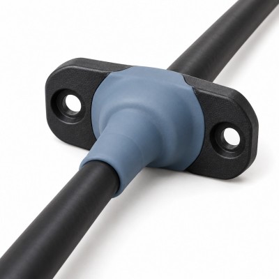
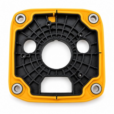
Mold Venting Design for Custom LSR Overmolding Quality
Mold venting is a small detail that can decide whether a custom LSR overmolding project runs smoothly or fails during sampling.
Liquid silicone rubber has excellent flowability, which makes it suitable for thin sealing lips, complex cavities, small ribs, soft-touch areas, and precision overmolded structures. However, when silicone flows into a mold cavity, the air inside the cavity must escape at the right time and through the right path.
If air cannot escape properly, it may create bubbles, short shots, burn marks, weak bonding areas, unstable surface quality, or incomplete sealing structures.
For silicone over plastic, silicone over metal, FPC silicone overmolding, connector seals, sensor parts, medical components, and waterproof electronic assemblies, mold venting should be reviewed before tooling. It is not only a production adjustment. It is part of the mold design and DFM process.
Answer Excerpt
Mold venting design in LSR overmolding helps trapped air escape from the cavity during silicone injection. Proper venting can reduce bubbles, short shots, burn marks, weak bonding, flash, incomplete filling, and sealing defects. It is especially important for thin sealing lips, FPC protection areas, connector seals, waterproof parts, and precision silicone overmolded components.
What Is Mold Venting in LSR Overmolding?
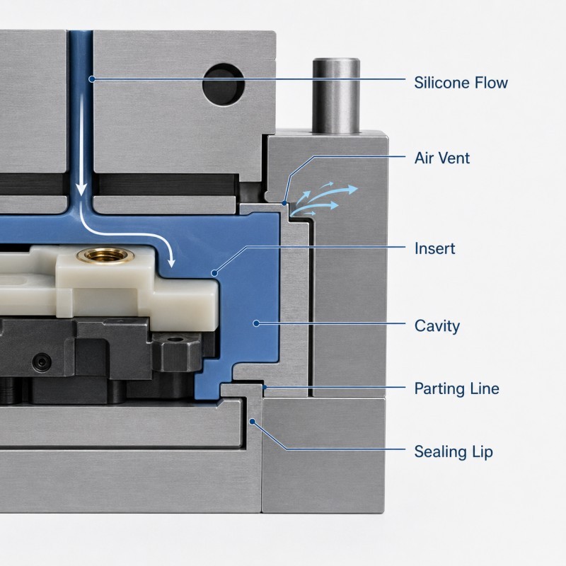
Mold venting is the design of small air escape paths inside the mold. These paths allow air to leave the cavity as liquid silicone rubber flows into the required shape.
In custom LSR overmolding, the cavity may contain a plastic insert, metal insert, FPC, cable, connector housing, sensor component, or another silicone part. Because the insert takes up space inside the mold, air can easily become trapped around corners, sealing lips, bonding edges, thin walls, and undercut areas.
A good venting design allows air to escape without allowing excessive silicone flash to form on functional surfaces.
The goal is to fill the cavity completely while keeping the final part clean, accurate, and stable.
Why Air Traps Happen During Overmolding
Air traps happen when silicone flow blocks the air inside the cavity before the air has a clear escape path.
This can occur in deep grooves, closed corners, thin sealing lips, narrow bonding areas, around inserts, and at the end of long flow paths.
In overmolding projects, the problem becomes more complex because the insert itself may block air movement. A plastic housing, metal terminal, FPC, or cable outlet can divide the mold cavity into small spaces where air becomes trapped.
Poor gate location, unbalanced flow, insufficient venting, high injection speed, and complex product geometry can all increase air trap risk.
If air traps are not solved at the mold design stage, the project may need repeated trial molding, mold modification, or manual defect sorting during production.
Common Defects Caused by Poor Venting
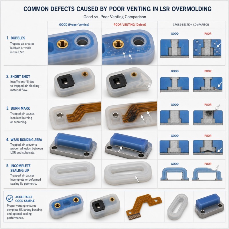
Poor mold venting may cause several quality problems in LSR overmolded parts.
Bubbles can appear inside or near the surface of the silicone layer. Short shots may occur when silicone cannot fully fill the cavity. Burn marks may appear when trapped air is compressed and heated. Weak bonding may happen if air remains between the silicone and substrate.
Poor venting may also cause incomplete sealing lips, rough edges, unstable appearance, uneven silicone thickness, and flash in the wrong location.
For waterproof sealing parts, even a small incomplete area can create leakage risk. For FPC parts, trapped air near the circuit protection zone may reduce sealing and insulation reliability. For medical or wearable components, visible bubbles or rough surfaces may be unacceptable.
Venting Must Match the Silicone Flow Direction
Mold venting should be designed together with silicone flow direction. It is not enough to add vents randomly.
Engineers should first understand where silicone enters the cavity, how it flows around the insert, which areas fill first, and where air is likely to be pushed.
The vent should usually be placed near the end of the flow path or in areas where air naturally accumulates. If the vent is placed in the wrong position, air may still remain trapped even when the mold has venting features.
For complex overmolded parts, flow balance is important. If one side fills too quickly, silicone may trap air on the other side. If the flow path is too long or too narrow, the final area may not fill completely.
A good design should consider gate position, flow direction, vent location, insert shape, wall thickness, and functional sealing surfaces together.
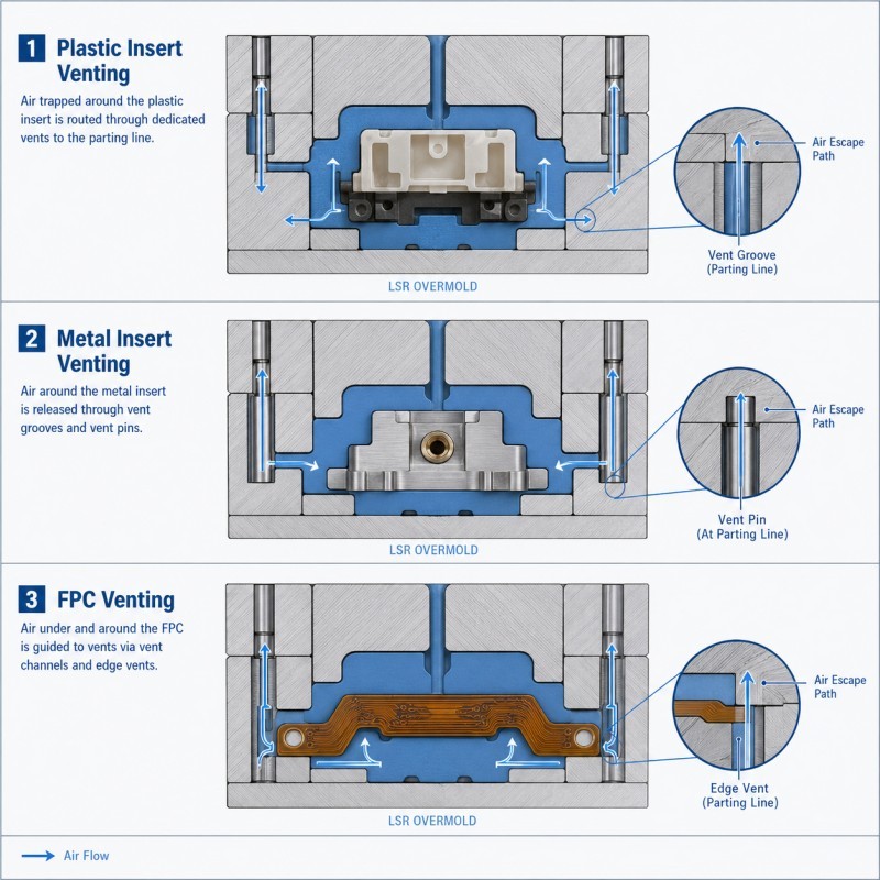
Venting for Plastic, Metal, and FPC Inserts
Different inserts create different venting challenges.
For silicone over plastic parts, air may be trapped around housing grooves, ribs, thin walls, button openings, connector edges, and sealing lips. The plastic insert may also deform if pressure builds up in a poorly vented area.
For silicone over metal parts, air may remain around pins, terminals, sharp edges, holes, grooves, or mechanical locking features. These areas often need controlled venting to avoid bubbles and weak bonding.
For FPC silicone overmolding, air may be trapped near solder joints, transition zones, flexible circuit edges, and strain relief areas. Venting must be designed carefully because excessive pressure or poor flow can damage or shift the FPC.
For cable and connector overmolding, air often accumulates around cable outlets, back ends, sealing grooves, and strain relief transitions.
Flash Control and Venting Balance
Venting and flash control must be balanced carefully.
If the vent is too small or blocked, air may not escape completely. If the vent is too large, liquid silicone rubber may flow into the vent and create flash.
For precision LSR overmolded parts, flash can be a serious issue. Flash on a sealing lip may affect waterproof performance. Flash on a button edge may affect pressing feel. Flash near a connector interface may cause assembly interference. Flash around an FPC area may affect appearance or flexibility.
This is why vent depth, vent width, parting line position, shut-off design, clamping stability, and mold precision all matter.
A good venting design should release air while keeping flash within acceptable limits.
Venting Around Sealing Lips and Thin Structures
Thin sealing lips and small ribs are common in waterproof silicone overmolded parts. These features are often difficult to fill because the cavity space is narrow and air cannot escape easily.
If venting is poor, the sealing lip may have incomplete filling, bubbles, rough edges, or weak points. This can directly affect waterproof or dustproof performance.
Engineers should review the sealing lip height, thickness, flow direction, vent position, parting line, compression surface, and areas where flash is not allowed.
For small electronic components, even a minor venting problem can become a functional issue during assembly or testing.
Process Parameters Also Affect Venting Results
Even with a good mold design, process parameters can affect venting performance.
Injection speed, injection pressure, mold temperature, clamping force, curing time, material viscosity, insert temperature, and demolding timing may all influence how silicone fills the cavity and how air escapes.
If injection speed is too fast, air may become trapped before it can escape. If clamping force is unstable, venting and flash control may change during production. If the mold temperature is not stable, curing behavior and flow performance may vary.
Stable production requires both correct mold venting design and controlled molding parameters.
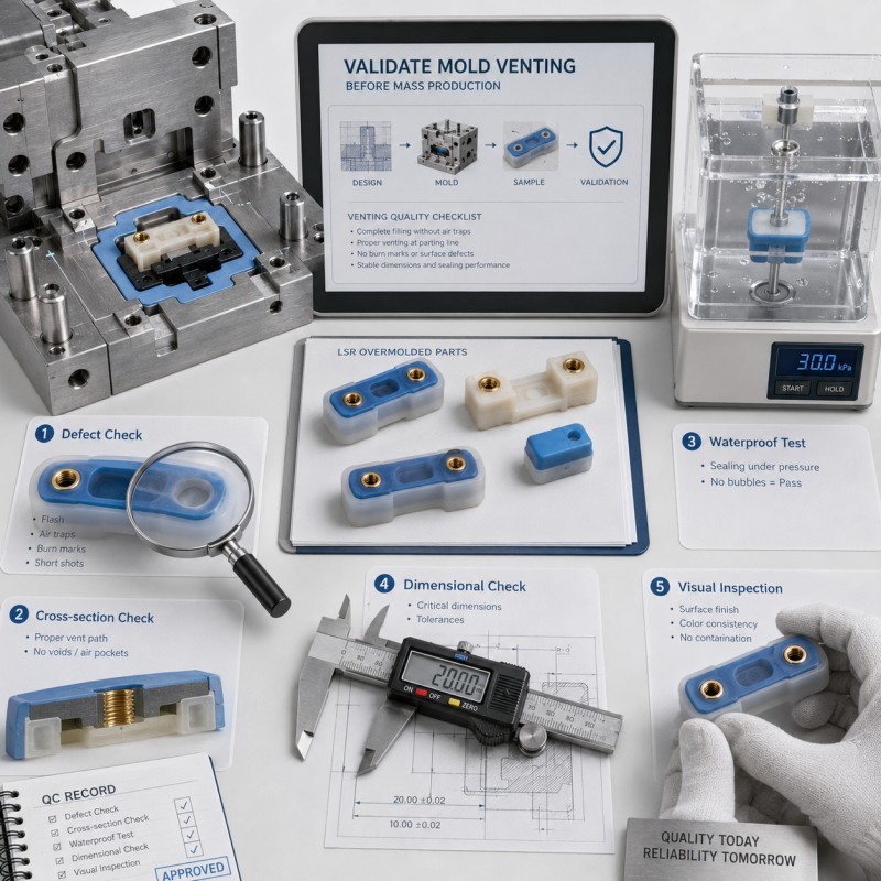
How to Validate Mold Venting Before Mass Production
Mold venting should be validated during trial molding and sample approval.
Engineers should check whether the silicone fully fills the cavity, whether bubbles appear near critical areas, whether sealing lips are complete, whether bonding edges are stable, and whether flash is controlled.
Common validation methods include visual inspection, cross-section inspection, dimensional inspection, waterproof test, air leakage test, bonding test, assembly test, and production repeatability check.
For precision overmolded parts, inspection should focus on functional areas rather than only the visible surface.
How SiliconePlus Supports Custom LSR Overmolding Projects
SiliconePlus supports custom LSR overmolding projects involving plastic, metal, FPC, silicone, cable, connector, and electronic insert structures. For mold venting and air trap control, our team can review drawings, samples, insert materials, silicone coverage areas, sealing structures, flow paths, venting locations, parting lines, and inspection standards before mold development.
We can support DFM review, silicone material selection, custom tooling, sample production, process optimization, inspection, and OEM/ODM mass production.
For automotive connector seals, medical electronic parts, wearable components, FPC protection structures, sensor modules, waterproof buttons, and industrial sealing components, early venting review can help reduce bubbles, short shots, flash problems, weak bonding, leakage risk, and unstable mass production.
Conclusion
Mold venting is a critical factor in custom LSR overmolding quality. It affects cavity filling, surface appearance, bonding stability, flash control, sealing performance, and mass production repeatability.
A successful venting design should consider silicone flow direction, gate position, insert structure, thin sealing lips, air trap areas, parting line position, vent size, flash control, and process stability before tooling.
If you are developing a custom LSR overmolded part with plastic, metal, FPC, cable, connector, sensor, or waterproof sealing structures, send us your drawings, samples, material information, testing standards, and estimated quantity. SiliconePlus can help evaluate the right overmolding solution from prototype to mass production.