Where Should the Mold Parting Line Be Placed on LSR Overmolded Seals?
Answer Excerpt
The mold parting line on an LSR overmolded seal should be positioned away from the primary sealing contact surface whenever the product structure allows it. A parting line can create a small ridge, mismatch or flash, and these features may interfere with uniform seal compression. The final location should therefore be reviewed together with sealing direction, mold shut-off, insert tolerance, venting, demolding and assembly conditions.
A mold parting line is the boundary where two mold sections meet.
For ordinary molded silicone products, a small parting-line witness may mainly be an appearance issue.
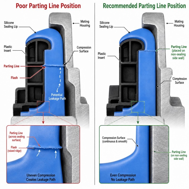
For waterproof LSR overmolded components, however, the same line may cross a sealing lip, compression surface, connector interface or water-blocking path.
This changes the problem from cosmetic to functional.
If the parting line produces flash, mismatch or a local step on the sealing surface, the mating component may not compress the silicone uniformly.
The product can then look completely acceptable before assembly but show leakage during air-pressure, immersion or environmental testing.
For waterproof projects, waterproof silicone seal design should therefore be reviewed before the mold parting line and shut-off surfaces are finalized.
Why Does Parting-Line Position Matter for Waterproof Sealing?
A waterproof seal works by maintaining continuous contact between the silicone and the mating surface.
The sealing path should not contain uncontrolled gaps.
A poorly positioned parting line may introduce:
• Silicone flash
• Mold mismatch
• A raised ridge
• A local depression
• Uneven sealing-lip thickness
• Trimming marks
• Surface damage
• Local compression variation
These problems become more serious when the line crosses the narrowest or highest-pressure sealing area.
For example, an axial sealing lip may depend on a continuous circular contact band. If a raised parting-line ridge crosses that band, the mating housing may compress the ridge first while nearby silicone receives less compression.
The opposite problem can also occur.
If manual trimming removes too much silicone from the parting-line area, a small local depression may develop and reduce sealing contact.
The objective is therefore not simply to make the parting line visually clean.
The objective is to keep it away from the most critical sealing path or control it tightly when relocation is impossible.
Where Should the Parting Line Be Avoided?
The parting line should normally be avoided on surfaces where a small ridge, flash or mismatch can directly affect product function.
High-risk locations include:
• Primary sealing lips
• Flat compression sealing lands
• Radial sealing surfaces
• Connector mating interfaces
• Waterproof plug surfaces
• Sensor sealing boundaries
• FPC contact or insertion areas
• Button movement surfaces
• Precision assembly datums
• Thin silicone edges
A primary sealing lip is particularly sensitive because its geometry is often narrow and intentionally flexible.
A small local defect can represent a large percentage of the total sealing-lip height.
The risk is also high around connector openings or functional holes because LSR can enter very small shut-off gaps.
When silicone reaches an opening, terminal or assembly surface, the result may be blocked installation, increased assembly force or electrical interference.
For precision projects, the parting-line location should be marked directly on the DFM drawing rather than decided only during tool manufacturing.
Where Should the Parting Line Be Placed Instead?
When possible, the parting line should be moved to a lower-risk surface that does not participate directly in sealing or precision assembly.
Better locations may include:
• Non-functional outer edges
• Hidden surfaces
• Areas outside the primary compression band
• Wider silicone sections
• Controlled cosmetic boundaries
• Regions supported by a rigid insert
• Areas where minor flash can be inspected easily
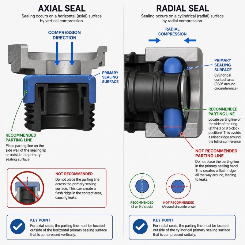
The best position depends on the direction in which the seal is compressed.
For an axial seal, the line should ideally stay away from the flat compression contact band.
For a radial seal, it should avoid creating a ridge around the circumference that directly contacts the mating bore.
For an overmolded connector, the parting line should also avoid electrical openings, terminal areas and critical insertion surfaces.
The location should be evaluated together with mold opening direction and demolding.
Moving the parting line away from the seal is not useful if the new tool structure creates a difficult undercut or tears the silicone during part removal.
How Do Insert Tolerances Affect the Parting Line?
In LSR overmolding, the mold may not close only against steel.
Some shut-off surfaces close directly against the plastic, metal, cable or FPC insert.
This means the insert itself becomes part of the flash-control system.
If a plastic housing is warped, too thin or positioned incorrectly, the mold may develop a small gap around the insert.
LSR can then enter that gap and create flash near the parting line.
Important insert variables include:
• Overall tolerance
• Flatness
• Local wall thickness
• Warpage
• Datum position
• Parting-line mismatch from the first molding process
• Insert positioning
• Heat deformation
• Supplier variation
This is why reducing flash cannot be solved only by increasing mold-clamping force.
The mold, insert and process must maintain stable contact across the realistic tolerance range.
Plastic with silicone overmolding should therefore be evaluated using the actual insert material, drawing tolerance and production sample variation.
Parting-Line DFM Checklist
| DFM Item | What Engineers Should Confirm | Main Risk |
Sealing direction | Axial, radial or another compression direction is defined | Parting line crosses primary contact area |
Sealing path | Continuous waterproof path is identified | Leakage path is overlooked |
Parting-line location | Line is outside critical sealing surfaces where possible | Flash affects compression |
Insert tolerance | Minimum and maximum insert conditions are reviewed | Shut-off gap changes |
Insert support | Insert cannot move or deform during injection | Local flash or mismatch |
Shut-off design | Stable mold contact area is available | Silicone enters protected areas |
| Venting | Air can escape without excessive flash | Bubbles or vent flash |
| Demolding | Seal can be released without tearing | Parting-line edge damage |
| Flash limit | Functional and cosmetic limits are defined | Buyer and factory use different standards |
The silicone mold design and tooling review should confirm the parting line, shut-off, gate, venting, sealing direction and insert support before mold steel is finalized.
How Should Parting-Line Quality Be Validated?
Parting-line quality should be validated on molded parts and final assemblies.
Recommended validation includes:
1. Visual Inspection
Inspect the complete parting line for flash, mismatch, tearing and uneven edges.
2. Dimensional Inspection
Measure critical seal height, compression surface and silicone boundary near the parting line.
3. Magnified Inspection
Use magnification where small flash or mismatch can affect a functional area.
4. Assembly Test
Confirm that the parting line does not increase insertion force, roll the sealing lip or interfere with the mating component.
5. Leak Testing
For waterproof components, test the completed assembly rather than only the loose overmolded part.
6. Thermal and Mechanical Conditioning
Repeat leak testing after thermal cycling, vibration, compression or repeated assembly when required by the application.
7. Multi-Cavity Validation
Compare every mold cavity because parting-line flash and mismatch may not be identical between cavities.
8. Consecutive Production Cycles
Confirm that the result remains stable as the mold reaches normal production temperature.
One visually good sample is not sufficient evidence of a stable mass-production parting line.
How SiliconePlus Supports LSR Seal DFM
SiliconePlus supports custom LSR overmolding projects from sealing-structure review through tooling, sampling, inspection and mass production.
Project support can include:
• Sealing-path analysis
• Parting-line positioning review
• Insert-tolerance review
• Mold shut-off design
• Gate and venting review
• Insert-positioning and support design
• Silicone thickness and sealing-lip review
• Precision mold manufacturing
• LSR injection molding
• Flash and dimensional inspection
• Assembly and waterproof test support
• Pilot-production validation
SiliconePlus has 25 years of silicone manufacturing experience, more than 6,000 developed silicone projects, in-house CNC and EDM mold-processing capability, liquid silicone injection equipment and precision inspection resources.
Specific flash limits, sealing tolerances and waterproof requirements should be confirmed according to the actual product structure, mating component and agreed test conditions.
FAQ
Can a Parting Line Be Placed on a Sealing Surface?
It may sometimes be unavoidable, but the risk must be evaluated carefully. Flash, mismatch and dimensional limits should then be controlled more strictly.
Is Every Visible Parting Line a Defect?
No. A visible witness line may be acceptable on a non-functional surface if it remains within the approved appearance standard.
Why Does a Parting Line Cause Leakage?
The line itself is not automatically a leakage path. The risk comes from flash, mismatch, local steps, damage or compression variation at the sealing interface.
Can Manual Trimming Solve Parting-Line Flash?
Manual trimming may be suitable for some non-critical areas, but it can introduce dimensional variation or surface damage. Critical sealing surfaces should not depend on uncontrolled manual trimming.
Can Higher Clamping Force Remove Parting-Line Flash?
Not necessarily. Flash may result from insert tolerance, warpage, poor shut-off, local pressure, mold wear or positioning problems.
Should the Parting Line Be Reviewed Before Tooling?
Yes. Moving the parting line after mold manufacturing may require significant tooling changes, especially when the seal geometry and demolding direction are affected.
Conclusion
The mold parting line on an LSR overmolded seal should be treated as a functional design feature rather than only a cosmetic boundary.
Reliable design requires coordinated control of:
• Sealing direction
• Sealing path
• Parting-line location
• Insert tolerance
• Mold shut-off
• Insert support
• Gate and venting
• Flash limits
• Demolding
• Assembly and leak testing
The best time to define the parting line is during DFM, before mold manufacturing begins.