Automotive Silicone Encapsulation vs LSR Overmolding: What’s the Difference?
Answer Excerpt
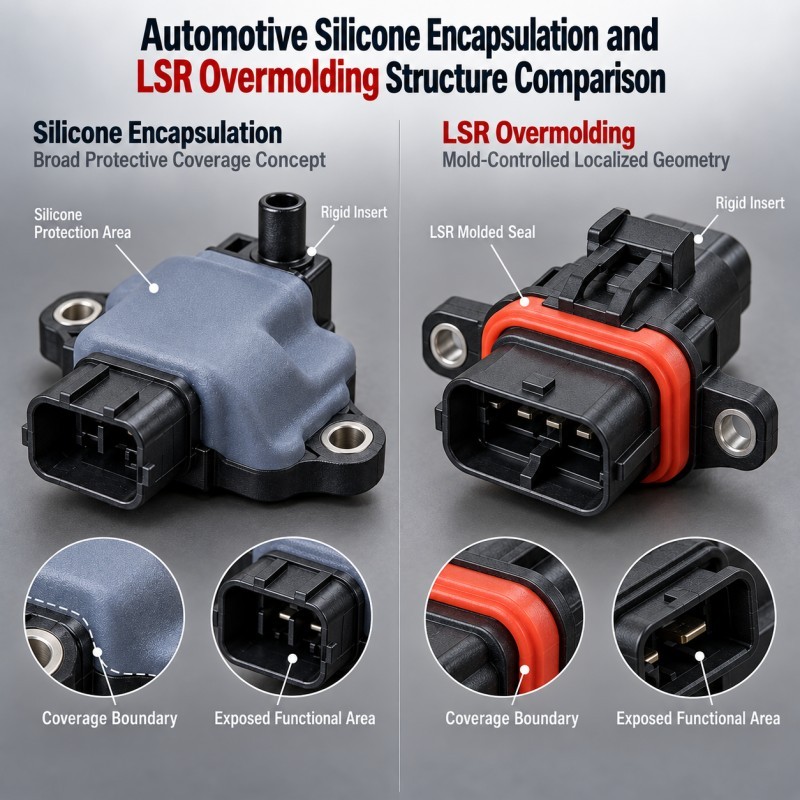
Automotive silicone encapsulation and LSR overmolding are related concepts, but they are not always the same manufacturing process.
“Silicone encapsulation” broadly describes using silicone to protect, seal, insulate or mechanically support an automotive component.
Depending on the product architecture, encapsulation may refer to different manufacturing approaches.
LSR overmolding is more specific.
A plastic, metal, connector, sensor carrier or other insert is positioned inside a precision mold, and liquid silicone rubber is molded onto defined areas to create a controlled silicone structure.
This approach is especially useful when engineers need:
• Precisely defined silicone coverage
• Integrated sealing lips
• Controlled exposed functional areas
• Repeatable silicone thickness
• Stable insert positioning
• Reduced loose-gasket assembly
• High-volume production repeatability
For automotive electronics, the correct question is therefore not simply:
“Should we encapsulate this component?”
It is:
“What areas need silicone protection, what areas must remain exposed, and which manufacturing process can reproduce that structure consistently?”
What Does Automotive Silicone Encapsulation Mean?
In automotive electronics, silicone encapsulation generally describes using silicone around a component to provide one or more protective functions.
Possible functions include:
• Moisture protection
• Dust protection
• Electrical insulation
• Vibration damping
• Strain relief
• Environmental protection
• Sealing around interfaces
• Mechanical cushioning
However, the word “encapsulation” alone does not define how the silicone is applied.
For one product, silicone may need to cover a large protective area.
For another product, only a narrow sealing perimeter should contain silicone.
A connector may require open terminal cavities.
A sensor may require an exposed sensing surface.
A mounting component may require metal holes, electrical contacts or datums to remain completely free of silicone.
That is why the required silicone coverage should be defined from the product function before a manufacturing method is selected.
How Is LSR Overmolding Different?
LSR overmolding uses a controlled mold cavity to form silicone directly onto selected areas of a rigid or flexible insert.
During LSR injection molding, the insert is positioned inside the mold, the mold closes around defined shut-off surfaces, and liquid silicone fills only the intended silicone cavity.
This makes it possible to control features such as:
• Sealing lips
• Perimeter gaskets
• Cable strain-relief zones
• Local protective layers
• Mechanical locking structures
• Soft-to-hard transitions
• Controlled silicone thickness
• Defined no-silicone areas
LSR overmolding is therefore particularly useful when the silicone itself has a precise three-dimensional function rather than simply acting as a general protective material.
When Is LSR Overmolding a Better Fit for Automotive Electronics?
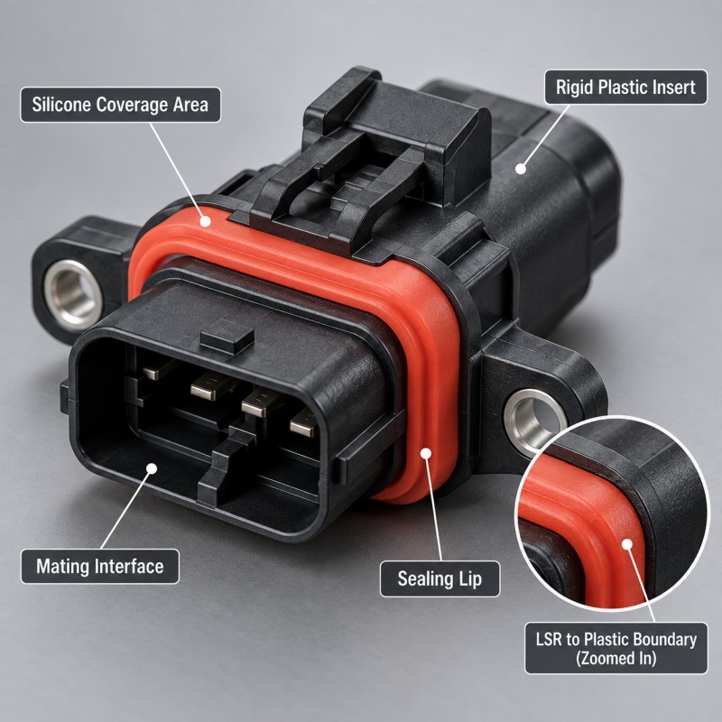
Automotive silicone overmolding is usually worth evaluating when a component requires repeatable silicone geometry around a defined plastic, metal or electronic structure.
Typical situations include:
• Connector interface sealing
• Sensor housing sealing
• Wire-harness interfaces
• Cable strain relief
• Charging interfaces
• Battery-related electronic interfaces
• Local vibration protection
• Plastic or metal carriers with integrated seals
The main advantage is not simply that silicone is attached to another material.
The important benefit is that the silicone location, geometry and functional boundary can be created as part of the molded component.
SiliconePlus currently uses this manufacturing direction for automotive connector, wire-harness and automotive-electronics sealing applications.
1. Define the Silicone Coverage Boundary First
The first engineering decision is not silicone hardness or color.
It is the exact boundary between:
• Silicone-covered areas
• Exposed plastic areas
• Exposed metal areas
• Electrical interfaces
• Connector cavities
• Mounting surfaces
• Sensor surfaces
• Inspection datums
This boundary should be visible in the 3D model or drawing.
A vague note such as “encapsulate this area with silicone” is often not enough for precision overmolding.
The drawing should clearly identify where the silicone begins, where it stops and which surfaces must remain completely free of silicone.
This is especially important near electrical and mating interfaces.
Even a thin unwanted silicone film can affect connector engagement, electrical contact or final assembly.
2. Do Not Encapsulate Functional Areas That Must Remain Exposed
More silicone coverage does not automatically create a more reliable automotive component.
Some areas must remain exposed to perform their function.
Examples include:
• Terminal openings
• Electrical contact areas
• Connector mating cavities
• Sensor faces
• Threaded holes
• Mounting datums
• Locking features
• Grounding surfaces
These should be treated as controlled no-silicone zones.
The mold must create a reliable shut-off around the boundary while the insert itself remains accurately positioned.
If the insert moves or the shut-off condition varies, silicone may enter an area that was intended to remain open.
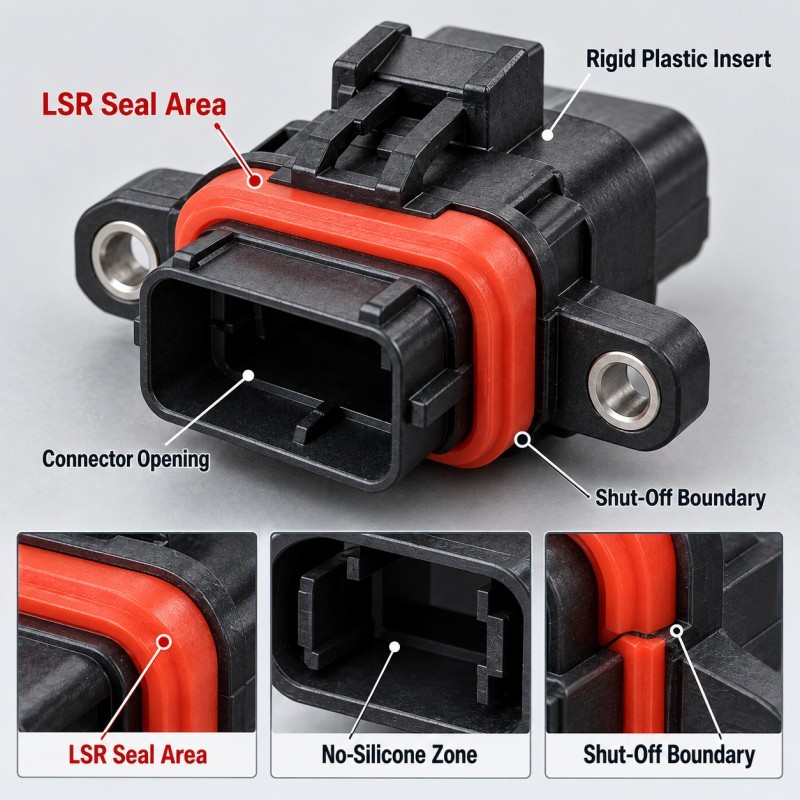
3. Connector Encapsulation Must Preserve the Mating Interface
Connector components are a good example of why controlled overmolding is different from simply covering a component with silicone.
Silicone overmolded connectors may need a molded sealing structure around the connector housing while the following areas remain exposed:
• Terminal cavities
• Mating openings
• Locking structures
• Assembly datums
• Electrical contact regions
The silicone may form a perimeter seal, face seal, terminal sealing region or local protective structure depending on the connector architecture.
For integrated connector sealing, the silicone geometry must be evaluated together with the mating component and the required compression condition.
4. Plastic, Metal and Electronic Inserts Need Different Strategies
The insert material changes how an automotive overmolding project should be designed.
For plastic inserts, engineers may need to review:
• Heat resistance
• Warpage
• Mold shrinkage
• Silicone compatibility
• Shut-off surfaces
• Mechanical retention
For metal inserts, important factors may include:
• Metal grade
• Surface condition
• Plating
• Oil or contamination
• Burrs and sharp edges
• Bonding requirements
For flexible or electronic inserts, engineers may also need to review:
• Insert support
• Bending-sensitive zones
• Electrical contacts
• Pressure-sensitive areas
• Required exposed regions
The complete material combination should therefore be reviewed before tooling rather than treating all automotive encapsulation projects as the same process.
5. Sealing Geometry Must Be Designed Around the Final Assembly
A molded silicone structure can look complete and still fail after assembly if the sealing geometry does not match the mating component.
For sealing applications, engineers should evaluate:
• Sealing path
• Silicone contact area
• Compression direction
• Minimum and maximum compression
• Assembly stops
• Housing tolerance
• Insert tolerance
• Parting-line position
• Local flash risk
The silicone geometry should be designed around the complete assembled system.
This is one reason an isolated silicone sample is not sufficient to prove final automotive waterproof performance.
The mating housing, rigid insert and final assembly force can all change how the seal behaves.
6. Thermal Cycling and Vibration Test the Complete Interface
Automotive overmolded components may experience repeated temperature changes and mechanical vibration during service.
The silicone and insert do not necessarily respond to these conditions in the same way.
Potential risks include:
• Interface peeling
• Edge lifting
• Cracking near rigid transitions
• Insert deformation
• Loss of sealing pressure
• Cable movement
• Local stress around sharp features
This is why automotive validation should evaluate the complete overmolded assembly rather than only the silicone material.
The required test conditions should be defined by the actual customer project, product location and application environment.
Automotive Encapsulation vs LSR Overmolding: Quick Comparison
| Engineering Question | General Silicone Encapsulation | LSR Overmolding |
Meaning | Broad protection concept | Specific precision molding process |
Silicone geometry | Depends on selected process | Defined by mold cavity |
Insert required | Not always | Normally uses a preformed insert |
Coverage boundary | May be broad or local | Precisely controlled |
No-silicone zones | Process dependent | Can be designed with mold shut-offs |
Sealing lips | Depends on process | Well suited to molded functional geometry |
| Mass-production repeatability | Depends on process | Designed for repeatable molding |
| Tooling requirement | Depends on method | Precision mold required |
| Typical automotive use | General protection or insulation concepts | Connectors, sensors, housings, carriers, cable interfaces |
How Should Automotive Overmolded Parts Be Validated?
Validation should match the actual automotive function.
Depending on the project, the validation plan may include:
• Dimensional inspection
• Silicone coverage inspection
• Insert-position inspection
• Bonding evaluation
• Assembly verification
• Leak or waterproof testing
• Thermal cycling
• Vibration testing
• Pull or strain-relief testing
• Electrical-interface inspection
• Pilot-production repeatability
A sample that looks visually complete is not enough.
The project should confirm that critical functional areas remain exposed, silicone boundaries remain stable and the complete assembly continues to perform after the required environmental and mechanical tests.
How SiliconePlus Supports Automotive LSR Overmolding Projects
SiliconePlus supports custom automotive silicone parts and LSR overmolding projects from engineering review through tooling, sampling and mass production.
Project review can include:
• Insert structure evaluation
• Silicone coverage definition
• No-silicone-zone review
• Plastic or metal substrate evaluation
• Seal geometry discussion
• Mold shut-off feasibility
• Gate and venting review
• Insert positioning
• Dimensional inspection planning
• Assembly and sealing validation
The goal is not to cover as much of the automotive component as possible.
The goal is to place silicone only where it creates a required sealing, protection, insulation, strain-relief or mechanical function while preserving every necessary exposed interface.
FAQ
Is Automotive Silicone Encapsulation the Same as LSR Overmolding?
No. Silicone encapsulation is a broader protection concept. LSR overmolding is a specific molding process in which liquid silicone rubber is molded onto defined areas of a pre-positioned insert.
Can LSR Overmolding Leave Connector Openings Exposed?
Yes. The mold can be designed with controlled shut-off areas so that terminal openings, connector cavities and other functional zones remain exposed while silicone is molded around the required sealing region.
Can LSR Be Overmolded Onto Both Plastic and Metal Automotive Parts?
Potentially yes, but material compatibility, surface condition, bonding strategy, insert positioning and tooling requirements must be evaluated for the actual substrate and application.
Does More Silicone Coverage Improve Waterproof Performance?
Not necessarily. Waterproof performance depends on the correct sealing path, compression, interface design, material combination, mold control and final assembly. Unnecessary silicone coverage can create new tooling or assembly problems.
Conclusion
Automotive silicone encapsulation should begin with the function that needs protection, not with the assumption that the entire component should be covered in silicone.
For applications requiring precise silicone geometry, controlled sealing boundaries and repeatable exposed functional areas, LSR overmolding can provide a practical manufacturing approach.
A successful project requires engineers to define:
• The real silicone coverage area
• Required exposed zones
• Insert material
• Sealing geometry
• Bonding or retention strategy
• Mold shut-off condition
• Assembly requirements
• Validation conditions
The correct solution is the one that protects the required automotive function while remaining manufacturable and repeatable in mass production.
Developing an Automotive Silicone Overmolding Project?
If you are developing an automotive connector, sensor, housing, cable interface or other silicone overmolded component, send your 2D/3D drawing, insert material, required silicone coverage, exposed functional areas, sealing requirements and estimated production quantity to our engineering team.
You can contact SiliconePlus to review the part structure, LSR overmolding feasibility, tooling concept and validation requirements before mold development.