Can Adhesive-Bonded FPC Stiffeners Survive LSR Overmolding?
Answer Excerpt
Adhesive-bonded FPC stiffeners can be compatible with LSR overmolding, but compatibility depends on the complete flexible-circuit construction, adhesive chemistry, actual thermal exposure, mold pressure and silicone coverage geometry. A stiffener that survives normal FPC assembly is not automatically qualified for an additional silicone molding cycle. Engineers should verify the adhesive bond, coverlay integrity, exposed electrical contacts and circuit function before approving tooling. When the existing stack-up cannot tolerate the process, the stiffener position, bonding method or overmolding sequence may need to change.
What Does LSR Overmolding Actually Expose in an FPC Assembly?
A flexible printed circuit is not a single uniform plastic sheet.
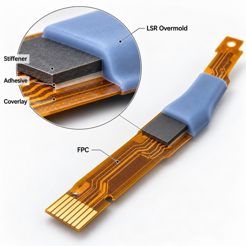
Depending on its construction, an FPC assembly may contain polyimide film, copper conductors, dielectric adhesive, coverlay, solder mask, exposed contact pads, local stiffeners, reinforcing adhesives and mounted electronic components.
These materials do not necessarily have the same thermal, mechanical or chemical limits.
During LSR overmolding, the FPC is placed inside a tool, and liquid silicone rubber is molded directly onto selected areas of the circuit or its supporting structure. The silicone is then cured under controlled processing conditions.
A simplified FPC stack-up may include:
- Flexible base film supporting copper traces.
- Coverlay and associated adhesive protecting selected conductor areas.
- A locally bonded stiffener supporting a connector, component or assembly feature.
- A specified silicone overmolding area providing sealing, protection or strain relief.
- Exposed contact pads, locating features and bending areas that must remain functional.
The critical distinction is that silicone-to-FPC adhesion and adhesion within the FPC stack-up are separate issues.
Even if the silicone remains properly attached, the stiffener may lift from its adhesive layer, the coverlay may separate, or an electrical connection may change.
For a real product category, review the [custom FPC silicone overmolded waterproof seal](https://www.siliconeplus.net/pid18562635/Custom-FPC-Silicone-Overmolded-Waterproof-Seal.htm). The product page illustrates localized silicone overmolding on a flexible circuit rather than a separately assembled rubber gasket.
SiliconePlus also provides [FPC with silicone overmolding manufacturing](https://www.siliconeplus.net/comm03/FPC-with-Silicone-Overmolding-Manufacturing-Solutions.htm) for drawing-based component development.
Not every FPC requires a stiffener, and not every stiffener needs to sit beneath the silicone. The exact construction should be confirmed before the mold is designed.
Why Can an FPC Stiffener Adhesive Fail During LSR Overmolding?
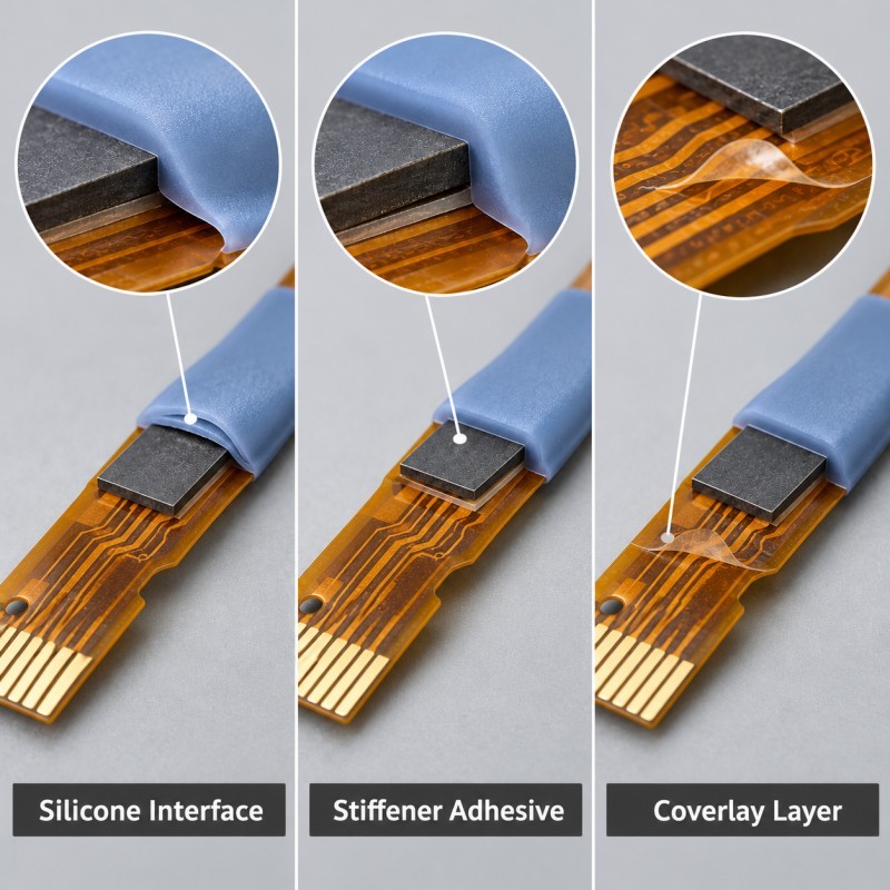
A bonded stiffener may perform correctly during incoming inspection and still develop problems during or after overmolding.
The main risk is the interaction between the original FPC fabrication process and the additional molding process.
1. The adhesive may not tolerate the actual thermal exposure.
A thermally bonded stiffener and a pressure-sensitive adhesive-backed stiffener are not automatically interchangeable.
Some adhesive systems are intended for elevated-temperature processing, while others are selected for convenient attachment after electronic assembly.
The critical variables include the adhesive manufacturer's approved temperature-time conditions, the prior curing or lamination history, the number of heat exposures and the actual temperature reached within the insert.
The FPC temperature cannot simply be assumed to equal a nominal machine setting.
2. Mold support and clamping can load the bonded interface.
If a stiffener is unsupported near its edge, mold closing force or silicone flow pressure may contribute to localized bending or peeling stress.
A raised stiffener edge may also create a gap that changes how the mold supports the surrounding flexible material.
3. The complete laminate can move differently under heat.
Copper, polyimide, coverlay, adhesive and the stiffener can respond differently to temperature changes.
If the local construction is not balanced, the FPC may bow or curl. This movement can create an unstable overmolding boundary or load the adhesive interface.
4. Trapped air or contamination may already exist in the bonded region.
A hidden void, incomplete adhesive coverage or contamination introduced before overmolding can become a failure initiation point.
Silicone molding should not be expected to repair an already weak FPC laminate.
5. The silicone termination can introduce secondary loading.
If a relatively thick silicone section ends directly at a stiffener edge, subsequent bending or handling may concentrate stress at the same location as the adhesive boundary.
A sample may therefore pass initial electrical inspection but fail after assembly or cyclic loading.
These mechanisms require different corrective actions. Increasing LSR bonding strength will not correct every failure within the flexible-circuit laminate.
The first task is to identify which interface has actually failed.
Should the Stiffener Be Bonded Before or After LSR Overmolding?
The process order should be chosen before finalizing the FPC drawing and the silicone mold.
There is no universal rule that every stiffener must be bonded before overmolding.
The decision depends on whether the stiffener provides a structural locating datum, sits beneath the intended silicone region, supports an electrical connector, or can be attached after the silicone component has been molded.
Three design routes are worth comparing.
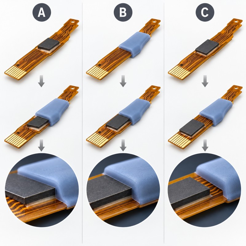
FPC Stiffener and LSR Overmolding Process Options
| Process Route | Sequence | Main Engineering Trade-Off |
| A. Pre-bonded stiffener | Fabricate FPC → bond and qualify stiffener → LSR overmolding | Enables the stiffener to support positioning, but adhesive and stack-up must tolerate molding exposure |
| B. Post-bonded stiffener | Fabricate FPC → LSR overmolding in a separate region → attach stiffener | Reduces thermal exposure of the final stiffener bond, but requires assembly access and compatible geometry |
| C. Revised carrier or reinforcement | Redesign local support and coverage → qualify structure → LSR overmolding | May avoid a vulnerable adhesive interface in the molded area, but changes the FPC and tooling design |
Route A: Qualify the pre-bonded stiffener.
This approach may be appropriate when the stiffener is essential for handling, locating or supporting the FPC during molding.
Before proceeding, the customer and molding supplier should confirm the stiffener material, attachment adhesive, laminate thickness, approved process temperature and acceptable bond condition after heat exposure.
A representative molded sample should be inspected for stiffener edge lifting, internal delamination, circuit distortion and electrical changes.
Route B: Attach the stiffener after LSR molding.
Post-bonding may be feasible when the stiffener sits outside the silicone coverage area and can still be installed using a controlled assembly process.
This approach must not compromise the final seal or require adhesive application over a critical silicone sealing interface.
Post-bonding is not a practical solution if the stiffener must be permanently enclosed inside an inaccessible silicone region.
Route C: Redesign local support.
When neither bonding sequence is suitable, the assembly may need a revised reinforcement structure, a different stiffener location or a compatible carrier concept.
This is a design change rather than a simple molding-parameter adjustment.
The most suitable route is the one that protects circuit function while producing a repeatable silicone feature and an inspectable finished assembly.
Process sequence should be confirmed during DFM review, not after a production tool has been completed.
How Should the Mold Protect the FPC Stack-Up?
Once the material stack-up has been reviewed, the mold should be designed around the actual flexible-circuit assembly.
A reliable FPC overmolding tool should not depend on clamping an adhesive boundary that cannot provide repeatable support.
Define the full FPC layer construction.
The DFM drawing should identify the overall FPC thickness, stiffener material, adhesive thickness, coverlay boundaries, component height, locating holes and silicone coverage map.
The nominal thickness alone may be insufficient if the stiffener and adhesive create local steps.
Use stable locating features.
A stiffener can sometimes serve as a locating reference, but only when its attachment and positional tolerance are suitable.
The process should avoid stretching the FPC between distant locating points or loading it in a permanently bowed condition.
General requirements for [insert positioning in LSR overmolding](https://www.siliconeplus.net/blog/How-Insert-Positioning-Affects-Custom-LSR-Overmolding-Quality_b27088) remain important, but the added stiffener interface requires its own support review.
Avoid concentrated clamping at adhesive edges.
Mold pressure should be supported by appropriate structural regions rather than a fragile, unsupported adhesive boundary.
If the FPC includes electronic components, mold clearance must protect those components while maintaining support near critical silicone shut-off regions.
Keep contact zones exposed.
Gold fingers, electrical contact pads, test points, connector insertion regions and required bending zones should remain clear wherever the final product design requires them.
Review [FPC gold-finger protection](https://www.siliconeplus.net/blog/How-Do-You-Protect-FPC-Gold-Fingers-and-Contact-Pads-During-LSR-Overmolding_b29277) separately from the adhesive qualification task.
The presence of a stiffener does not eliminate the need for a defined no-silicone zone.
Review gate flow and local cavity pressure.
The initial silicone flow should not push an unsupported FPC section into a different position or force a partially lifted stiffener edge farther away from its substrate.
The gate, venting, support surfaces and shut-off location should be reviewed together.
Protect the transition between reinforced and flexible regions.
A stiffener creates a local change in bending stiffness. The silicone thickness and termination should not unintentionally force repeated flexing into one narrow location.
The design should distinguish fixed protection areas from regions intended for dynamic bending.
Finally, demolding must not pull the finished component by an unsupported FPC tail or exposed connector end.
A mold that makes an attractive silicone shape but damages the internal flexible circuit is not a production-ready solution.
Which Tests Separate Adhesive Damage From Silicone Bonding Failure?
Before approving a silicone-overmolded FPC assembly, engineers should evaluate the laminate and the silicone structure separately.
The key is to establish a baseline before exposing the FPC to the overmolding process.
Step 1: Record the incoming FPC condition.
Inspect the stiffener position, flatness, bond-line appearance, exposed contact pads and critical dimensions.
Complete a project-defined electrical baseline test before molding.
Where appropriate, retain representative incoming samples for destructive examination.
Step 2: Evaluate representative thermal exposure.
The test should reflect the actual material and process under consideration.
A thermal-only witness sample can help distinguish heat-related adhesive damage from effects that occur when mold clamping and silicone flow are also present.
The test should account for the adhesive supplier's data, previous manufacturing exposures and the intended LSR processing cycle.
Step 3: Inspect the molded FPC assembly.
Look for stiffener lifting, coverlay separation, local curling, adhesive squeeze-out, cracked traces, displaced pads and abnormal silicone boundaries.
A cosmetic inspection should not replace functional testing.
Step 4: Identify the failure interface.
A lifting silicone edge is different from separation between a stiffener and the FPC.
An intact silicone shell can sometimes conceal internal laminate damage. Representative sectioning or other approved inspection methods may therefore be required.
Step 5: Repeat the relevant functional tests.
The finished assembly should be checked according to its intended use, including electrical continuity, insulation where applicable, connector fit, dimensional requirements and any defined sealing tests.
Project-specific environmental testing may be required if thermal cycling, moisture exposure or repeated bending can affect the assembly.
For related engineering principles, review [thermal cycling failures in LSR overmolding](https://www.siliconeplus.net/blog/Why-Do-LSR-Overmolded-Parts-Crack-or-Delaminate-After-Thermal-Cycling_b28017).
Passing an initial molding trial is not the same as qualifying the complete FPC construction for long-term service.
The acceptable test conditions and pass/fail criteria must be defined by the customer's product requirements.
FPC Stiffener Overmolding Validation Matrix
| Validation Item | Inspection or Test | Main Failure to Detect |
Incoming construction | Stack-up, adhesive type, stiffener position and thickness review | Uncontrolled material variation |
Thermal-only exposure | Representative heat exposure with agreed inspection | Heat-related adhesive degradation or warpage |
Molded sample inspection | Visual, dimensional and section review where appropriate | Lifting, internal separation or edge movement |
Adhesive bond | Project-defined adhesion or peel evaluation | Stiffener-to-FPC bond failure |
Silicone interface | Silicone coverage, edge and adhesion assessment | Silicone-to-FPC separation |
Electrical function | Before-and-after continuity and required functional testing | Damaged traces or contacts |
| Flex or assembly loading | Project-defined handling, bend or assembly evaluation | Stress at reinforced transitions |
| Environmental durability | Defined humidity, temperature or chemical exposure followed by retesting | Latent interface or functional degradation |
| Production consistency | Representative insert batches and consecutive molding trials | Process sensitivity and repeatability problems |
What Should the Customer Include in an FPC Overmolding RFQ?
A useful FPC silicone overmolding RFQ should contain more than an outer-shape drawing and a silicone hardness target.
The supplier needs enough information to evaluate the real assembly before proposing a mold structure or production process.
Recommended inputs include:
1. The 2D drawing and, where available, 3D model of the complete FPC assembly.
2. The FPC layer stack-up, including base film, conductor, coverlay and adhesive information.
3. Stiffener material, thickness, location and attachment method.
4. Adhesive supplier, material identification and approved processing conditions.
5. Prior soldering, lamination, cleaning and thermal processing history.
6. The required silicone coverage area, sealing boundary and no-silicone zones.
7. Required electrical contacts, connector clearance and bending regions.
8. Any mounted electronic components and their processing limits.
9. The expected assembly and operating environment.
10. Defined electrical, mechanical and sealing validation requirements.
11. Prototype quantity, estimated annual demand and inspection requirements.
If adhesive information is unavailable, the supplier should identify it as an unresolved qualification item rather than assume compatibility.
During the DFM stage, the customer and supplier can review the material interface, insert support, mold shut-off, silicone geometry and available process window.
SiliconePlus offers [liquid silicone injection molding](https://www.siliconeplus.net/comm17/Unlock-Innovation-with-Liquid-Silicone-Injection-Molding.htm) and custom overmolding support for suitable plastic, metal and FPC insert structures.
The final molding conditions and qualification plan must be established for the actual FPC and silicone material combination.
Frequently Asked Questions
Can pressure-sensitive adhesive stiffeners be used in LSR overmolding?
Possibly, but a pressure-sensitive adhesive should not be assumed suitable for the molding cycle. Its temperature-time limits, load conditions and bond stability must be checked against the actual process. Where compatibility cannot be established, a different bonding method or manufacturing sequence should be considered.
Does a polyimide FPC automatically tolerate LSR molding temperatures?
No. The base film may withstand certain thermal conditions, while the adhesive, coverlay, stiffener attachment or mounted components have different limitations. Qualification must consider the complete assembled FPC, not only the polyimide film.
Can a stiffener be attached after silicone overmolding?
Yes, when the final design leaves the attachment region accessible and the post-bonding operation does not compromise the silicone seal or circuit. If the stiffener is enclosed inside the intended silicone region, a post-bonding sequence may not be feasible.
How can engineers tell whether the adhesive or silicone has failed?
Inspect the actual separation interface. Silicone lifting from an intact coverlay indicates a different problem from a stiffener separating from its adhesive bond. Visual inspection, representative sectioning and project-defined adhesion tests can help identify the failure location.
Is a waterproof test enough to qualify an FPC stiffener assembly?
No. A finished assembly may meet its initial sealing requirement while still containing laminate damage or weakened adhesive. The qualification plan should also consider stiffener adhesion, electrical function, dimensional stability and relevant environmental or mechanical loading.
Conclusion
The central question in LSR overmolding on reinforced FPC is not whether silicone can cover a flexible circuit.
It is whether the complete FPC stack-up remains mechanically and electrically functional after the added manufacturing process.
Adhesive selection, stiffener location, actual thermal exposure, mold support, silicone termination and qualification testing should be reviewed as one system.
A sound engineering decision distinguishes three different interfaces:
- The bond between silicone and the FPC surface.
- The bond between the stiffener and the flexible circuit.
- The internal laminate interfaces within the FPC.
Each interface can fail differently and may require a different corrective action.
Before committing to tooling, confirm the FPC materials, evaluate feasible process sequences, test representative inserts and define the final assembly acceptance criteria.
The objective is a manufacturable, inspectable and project-qualified silicone-overmolded electronic component.
Discuss Your FPC Overmolding Project With SiliconePlus
Are you developing a flexible electronic component that requires localized silicone sealing or protection around a reinforced FPC?
SiliconePlus supports custom LSR overmolding projects involving flexible circuits and other suitable insert materials.
If your assembly includes bonded stiffeners, exposed contacts, sensitive components or critical bending regions, an early DFM review can help identify the information needed before tooling.
Send your FPC drawing, material stack-up, stiffener details, silicone coverage map, estimated quantity and required validation conditions.
Please [contact SiliconePlus](https://www.siliconeplus.net/contact-us.htm) to discuss the manufacturability of your custom FPC silicone overmolding project.