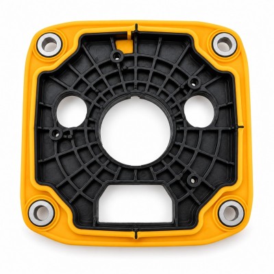
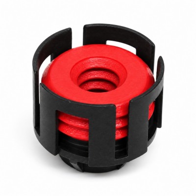
How Should Compression Stops Be Designed for LSR Overmolded Seals?
Answer Excerpt
A compression stop is a rigid feature that limits how far an LSR overmolded seal can be compressed when the final housing, connector or cover is assembled. A well-designed stop helps prevent both insufficient compression and excessive compression. It should be evaluated together with sealing-lip height, silicone hardness, mating gap, housing tolerance, assembly force and the real waterproof test condition.
Waterproof sealing does not depend only on making the silicone soft or tightening the assembly more strongly.
The sealing lip needs enough deformation to maintain continuous contact with the mating surface, but excessive compression can roll, flatten or permanently distort the silicone.
In an uncontrolled assembly, screw torque, snap-fit position, housing warpage or dimensional tolerance can determine how much the seal is compressed.
This means two products using the same silicone seal can experience different compression conditions.
A compression stop changes the assembly from an uncontrolled force-driven condition into a more controlled geometry-driven condition.
The rigid plastic or metal surfaces contact each other at the designed stop position, limiting additional closing movement while the silicone remains compressed within the intended working range.
For waterproof LSR projects, waterproof silicone seal design should therefore be reviewed together with compression-stop geometry before tooling begins.
Why Does an LSR Seal Need a Compression Stop?
A silicone seal needs a controlled final assembly gap.
Without a compression stop, the final gap may depend on:
• Screw torque
• Snap-fit force
• Housing stiffness
• Plastic warpage
• Operator assembly force
• Fastener sequence
• Insert tolerance
• Mating-part tolerance
These variables can change the actual seal compression from one assembly to another.
If the housing closes farther than intended, the sealing lip may be over-compressed.
If the housing stops too early, the seal may not generate enough contact.
A rigid compression stop provides a defined assembly endpoint.
Typical stop features may include:
• Plastic bosses
• Housing shoulders
• Metal spacers
• Connector body steps
• Molded support ribs
• Screw-column contact surfaces
• Controlled mating flanges
The stop should carry the final structural closing load rather than forcing the silicone to act as the only assembly limiter.
The exact design depends on whether the seal is axial, radial, peripheral or localized around a connector, sensor or electronic housing.
What Happens If the Compression Stop Is Too High?
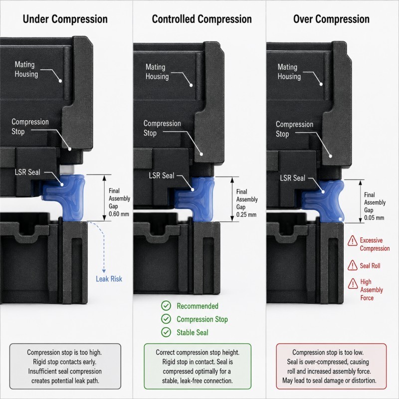
If the compression stop is too high, the mating parts contact the stop before the silicone seal has been compressed sufficiently.
Possible results include:
• Low sealing contact pressure
• Incomplete sealing around housing corners
• Leakage during pressure testing
• Greater sensitivity to plastic warpage
• Local gaps caused by tolerance variation
• Unstable sealing after vibration
• Failure after thermal cycling
The silicone may appear to touch the mating surface, but simple visual contact does not confirm that sufficient compression exists around the complete sealing path.
This is particularly risky with large housings and long peripheral seals.
A small dimensional difference at the rigid stop can change compression over a large section of the silicone seal.
The minimum-compression condition should therefore be checked using the worst-case combination of seal height, housing dimension, groove depth and compression-stop height.
What Happens If the Compression Stop Is Too Low?
If the compression stop is too low, the housing may continue closing after the silicone has already reached its intended deformation.
Possible results include:
• Sealing-lip rolling
• Silicone being pushed sideways
• Excessive assembly force
• Plastic housing deformation
• Bonding-edge stress
• Local silicone extrusion
• Difficult disassembly
• Reduced recovery after long-term loading
Excessive compression does not automatically improve waterproof performance.
The mating surface may initially seal very well, but excessive deformation can create uneven contact and increase long-term stress in the silicone and surrounding substrate.
Compression set is especially relevant for seals because the material must continue maintaining recovery after being held under deformation. LSR material suppliers therefore specifically characterize and develop low-compression-set grades for gasket and connector sealing applications. :contentReference[oaicite:3]{index=3}
The stop should therefore limit the maximum assembly movement before the sealing lip is crushed beyond its validated working condition.
Why Must Tolerance Stack-Up Be Included?
Compression-stop design cannot be based only on nominal CAD dimensions.
The final silicone compression may be affected by:
• Silicone seal height
• Silicone dimensional tolerance
• Plastic insert thickness
• Groove depth
• Housing flatness
• Compression-stop height
• Mating-part thickness
• Screw or snap position
• Insert warpage
• Mold cavity variation
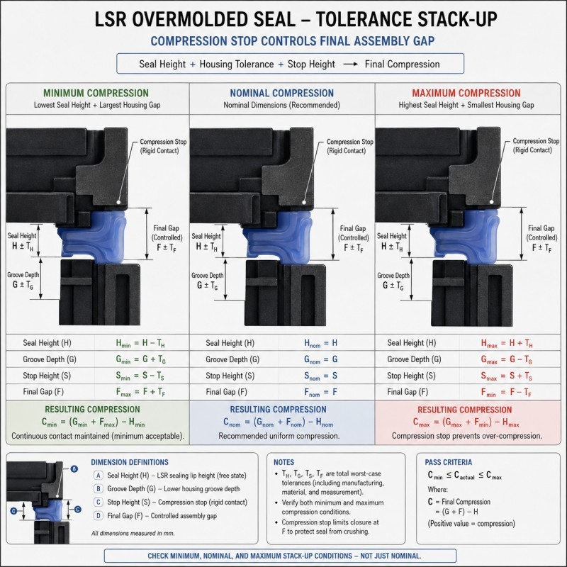
The DFM review should therefore evaluate at least three assembly conditions:
1. Minimum Compression Condition
The tolerance combination creates the largest available gap and the smallest silicone interference.
2. Nominal Compression Condition
All major dimensions are close to their nominal values.
3. Maximum Compression Condition
The tolerance combination creates the smallest available gap and the greatest silicone deformation.
A design that works only at nominal dimensions is not ready for mass production.
The minimum condition must still create a continuous sealing path, while the maximum condition must not excessively crush, roll or damage the silicone.
How Do Silicone Hardness and Seal Geometry Affect the Stop?
The same compression-stop gap cannot automatically be used for every silicone material or sealing-lip geometry.
A softer seal may deform more easily under assembly load.
A harder seal generally requires more force to reach the same geometric deformation.
Geometry also changes the effective stiffness.
Important factors include:
• Silicone hardness
• Lip height
• Lip width
• Root thickness
• Contact width
• Number of sealing lips
• Hollow or solid structure
• Compression direction
• Radius at the sealing-lip root
• Support from the plastic insert
For example, a tall narrow sealing lip can deform very differently from a short wide sealing bead even when both use the same Shore A hardness.
Changing only the silicone hardness may therefore change assembly force without solving an incorrect stop height.
Material hardness, seal geometry and compression-stop position should be reviewed together.
For material selection, review how to choose the right silicone hardness for LSR overmolding.
Compression Stop DFM Checklist
| DFM Item | What Engineers Should Confirm | Main Risk |
Seal function | Waterproof path and compression direction are defined | Stop controls the wrong area |
Seal geometry | Lip height, width and root are confirmed | Deformation becomes unstable |
Silicone hardness | Material is evaluated with geometry | Assembly force is incorrect |
Compression stop | Rigid final closing surface is defined | Assembly depends only on force |
Minimum condition | Seal still makes continuous contact | Leakage |
Maximum condition | Seal is not crushed or rolled | Permanent deformation |
| Housing tolerance | Flatness, groove and stop dimensions are reviewed | Uneven compression |
| Insert support | Plastic cannot bend near the stop | Local compression changes |
| Validation | Assembly, leak and aging tests are defined | Samples pass but field use fails |
The silicone mold design and tooling review should confirm seal geometry, compression-stop position, insert tolerance, groove depth, parting line and final assembly gap before mold steel is finalized.
How Should Compression Stops Be Validated?
Compression-stop validation should be completed on the final assembled product rather than only on the loose silicone component.
Recommended validation includes:
1. Assembly Gap Measurement
Confirm that the rigid compression stops reach the designed final position.
2. Seal Compression Inspection
Use section analysis, pressure-sensitive methods or controlled dimensional comparison where appropriate to confirm how the silicone deforms.
3. Assembly Force or Torque Review
Confirm that the product reaches the hard stop without excessive force or substrate deformation.
4. Leak Testing
Complete air-leak, pressure-decay, immersion or application-specific waterproof testing on the assembled product.
5. Minimum and Maximum Tolerance Samples
Evaluate assemblies representing low and high seal-compression conditions.
6. Heat Aging
Hold the assembled seal under compression and repeat the functional test after the defined aging condition.
7. Thermal Cycling
Confirm that housing and seal dimensional changes do not open the sealing path.
8. Multi-Cavity and Pilot-Production Validation
Compare multiple mold cavities and consecutive production cycles before approving mass production.
The target is not simply maximum compression.
The target is a stable compression window that continues sealing across realistic material, molding and assembly variation.
How SiliconePlus Supports LSR Seal Compression Design
SiliconePlus supports custom LSR overmolding projects from sealing-structure and tolerance review through tooling, sampling, inspection and mass production.
Project support can include:
• Sealing-path review
• Compression-stop DFM
• Silicone hardness review
• Seal-lip geometry analysis
• Plastic and insert tolerance review
• Mold shut-off and parting-line review
• Precision mold manufacturing
• LSR injection molding
• Dimensional inspection
• Assembly and waterproof test support
• Pilot-production validation
SiliconePlus has 25 years of silicone manufacturing experience, more than 6,000 developed silicone projects, CNC and EDM mold-processing capability, liquid silicone injection equipment and precision inspection resources.
FAQ
Is a Compression Stop Always Necessary?
Not every silicone seal requires a separate stop feature. However, the final compressed gap must still be controlled by a repeatable assembly structure rather than unpredictable force.
Can Screw Torque Control Silicone Compression?
Torque alone is not a reliable geometric control because friction, housing stiffness, screw condition and assembly variation may change the final position. A rigid stop provides a more repeatable endpoint.
Is More Seal Compression Better for Waterproofing?
No. Too little compression can create leakage, while too much can distort the seal, increase assembly force or reduce long-term recovery.
Should the Stop Touch Before the Silicone Is Compressed?
No. The silicone should reach its intended deformation before the rigid stop prevents additional closing movement.
Can Silicone Hardness Fix an Incorrect Stop Height?
Not reliably. Hardness changes force and deformation behavior, but an incorrect assembly gap should normally be corrected geometrically.
Should Compression Stops Be Tested After Heat Aging?
Yes when long-term compressed sealing performance is important. The seal should continue maintaining sufficient contact after the defined aging and environmental conditions.
Conclusion
A compression stop converts LSR seal compression from an uncontrolled assembly-force problem into a controlled geometric design condition.
Reliable compression-stop design requires coordinated control of:
• Seal geometry
• Silicone hardness
• Stop height
• Groove depth
• Housing tolerance
• Minimum compression
• Maximum compression
• Insert deformation
• Assembly force
• Leak and aging validation
The stop should prevent over-compression without allowing the sealing contact to become too low at the opposite tolerance condition.
The best time to define this structure is during DFM, before tooling.