How Should Dimensional Tolerances Be Defined for Flexible LSR Overmolded Parts?
Answer Excerpt
Dimensional tolerances for flexible LSR overmolded parts should be defined together with the measurement method. Engineers must specify the datum, measurement position, inspection force, temperature, conditioning time and whether the part is measured free, compressed or assembled. Because silicone deforms under contact pressure, two inspectors may obtain different results from the same acceptable part when the inspection method is not controlled.
Liquid silicone rubber overmolding can integrate sealing lips, soft-touch areas, flexible hinges, protective covers and vibration-damping structures directly onto plastic, metal, FPC or cable inserts.
However, flexible silicone parts cannot always be measured in the same way as rigid plastic or machined metal components.
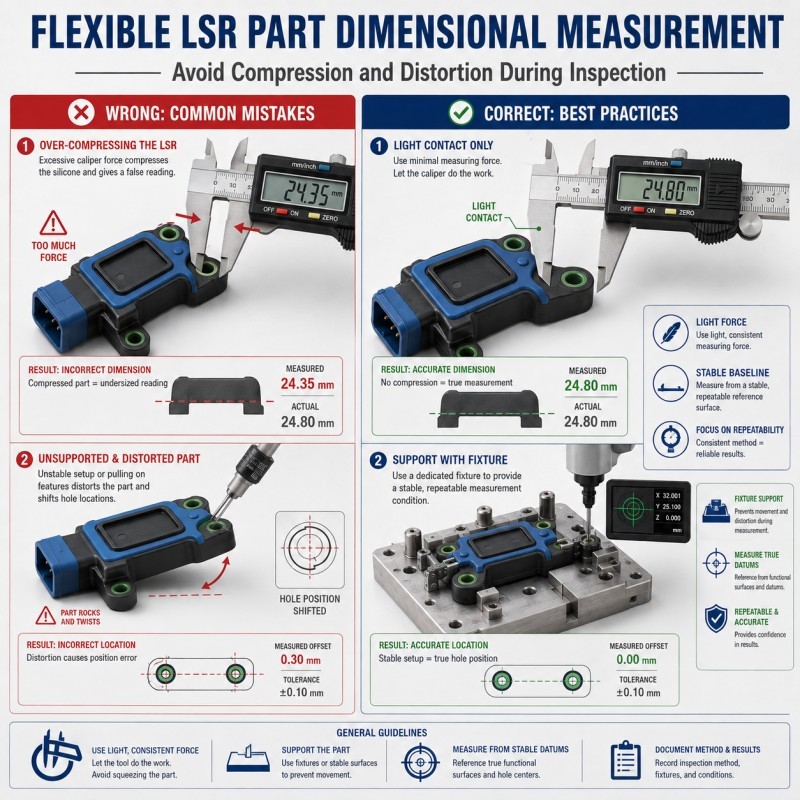
A caliper may compress a soft sealing lip. A thin overmolded edge may stretch when handled. A flexible hole may appear oval when the part is not supported correctly.
The measured value may therefore reflect the inspection method rather than the true molding condition.
For precision multi-material components, liquid silicone injection molding should be reviewed together with functional tolerances, measurement fixtures and final assembly requirements.
Why Do Flexible Silicone Measurements Vary?
Flexible silicone changes shape when it is touched, clamped, stretched, compressed or placed on an uneven surface.
Common causes of measurement variation include:
• Excessive caliper force
• Different measurement positions
• Unsupported sealing lips
• Stretching during handling
• Part temperature
• Insufficient conditioning time
• Incorrect datum selection
• Insert warpage
• Silicone shrinkage after molding
• Different cavity conditions
• Different inspector techniques
The softer and thinner the silicone structure is, the more sensitive the result may be to contact force.
This does not mean that dimensional control is impossible.
It means that the drawing and inspection standard must define how the part should be measured.
Which Dimensions Should Be Treated as Critical?
Not every dimension on an LSR overmolded part requires the same tolerance or inspection frequency.
Critical dimensions are normally those that affect:
• Seal compression
• Assembly fit
• Connector insertion
• Button travel
• Contact-pad exposure
• Waterproof performance
• Insert position
• Silicone coverage boundary
• Functional hole clearance
• Final product envelope
Reference dimensions may be used to describe the general shape but should not automatically receive the same tight tolerance as a sealing lip or assembly datum.
The drawing should identify:
1. Critical functional dimensions
2. Assembly dimensions
3. Cosmetic boundary dimensions
4. Reference dimensions
5. Dimensions controlled by the rigid insert
6. Dimensions controlled mainly by the silicone
A tolerance should be connected to a real product function. Applying unnecessarily tight tolerances to flexible, non-functional areas increases inspection disputes and production cost without improving the final product.
How Should Datums and Measurement Conditions Be Defined?
The measurement datum should come from the most stable part of the component.
For silicone over plastic, metal or FPC parts, the rigid insert is often a more repeatable datum than the flexible silicone edge.
The inspection standard should define:
• Primary datum
• Secondary datum
• Part orientation
• Support location
• Measurement position
• Contact force
• Measuring tool
• Product temperature
• Conditioning time
• Free or assembled measurement state
A sealing lip may need to be measured in a free state for mold control and again in an assembled or compressed state for functional validation.
A flexible hole may require a pin gauge or optical measurement instead of direct caliper measurement.
A long soft edge may require a fixture that supports the part without stretching it.
The same method should be used during sample approval, incoming inspection and mass-production inspection.
Common Measurement Mistakes
Common inspection mistakes include:
• Compressing a soft seal with caliper jaws
• Measuring a flexible hole while pulling the part
• Using an unstable silicone edge as the datum
• Comparing a warm molded part with a conditioned sample
• Measuring only one mold cavity
• Measuring different points on different samples
• Ignoring insert warpage
• Applying rigid-plastic tolerances to unsupported silicone features
• Approving one manually adjusted sample as the production standard
Where possible, non-contact optical measurement should be used for small flexible features.
Dedicated fixtures, pin gauges, profile projectors or coordinate systems may also be required depending on the product structure.
For projects where flash and dimensional variation occur together, review how to control flash and tolerance in LSR overmolding.
Dimensional Tolerance and Inspection Checklist
| Inspection Item | What Must Be Defined | Recommended Control |
Functional dimension | Effect on sealing, assembly or electrical function | Mark as a critical dimension |
Datum | Stable reference surface or insert feature | Avoid flexible unsupported edges |
Measurement state | Free, supported, compressed or assembled | Use the same state for approval and production |
Inspection force | Contact pressure applied by the tool | Use light contact or a controlled fixture |
Measuring tool | Caliper, optical system, pin gauge or fixture | Match the tool to the flexible geometry |
Conditioning | Time and temperature before inspection | Define a consistent conditioning period |
| Cavity identification | Mold cavity producing each sample | Record and compare cavity-specific results |
| Insert position | Plastic, metal, FPC or cable location | Measure from stable insert datums |
| Sample quantity | Number of parts and production cycles | Include consecutive cycles and multiple lots |
Acceptance record | Drawing, method, samples and results | Keep a traceable inspection standard |
The silicone mold design and tooling review should define which dimensions are controlled by the mold cavity, which depend on the insert and which require a dedicated inspection fixture.
How Should Dimensional Stability Be Validated?
Dimensional approval should be based on repeated production results rather than one selected sample.
Recommended validation includes:
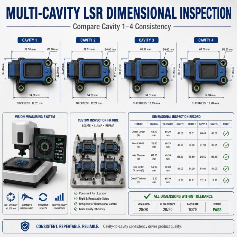
1. Measure Every Mold Cavity
Record cavity numbers and compare critical dimensions between cavities.
2. Run Consecutive Molding Cycles
Confirm whether dimensions change as the mold and inserts reach stable production temperature.
3. Inspect Multiple Insert Lots
Plastic, metal, FPC or cable variation may change the final overmolded dimensions.
4. Compare Free and Assembled Conditions
A dimension that varies in the free state may still perform correctly after controlled assembly. Functional testing should confirm this.
5. Complete Capability Review
For critical dimensions, evaluate process consistency rather than relying only on minimum and maximum samples.
6. Repeat After Environmental Exposure
Thermal cycling, humidity, compression or fluid exposure may change the final dimensions or seal recovery.
7. Approve the Measurement Method
The customer and manufacturer should use the same fixture, datum, tool and acceptance method.
A dimensional report is only meaningful when the inspection method is repeatable.
How SiliconePlus Supports Dimensional Control
SiliconePlus supports custom LSR overmolding projects from drawing and tolerance review through tooling, sampling, inspection and mass production.
Project support can include:
• Critical-dimension identification
• Silicone and insert tolerance review
• Datum and measurement-method planning
• Mold-cavity and insert-position analysis
• Dedicated inspection-fixture development
• Precision mold manufacturing
• LSR injection molding
• Optical and dimensional inspection
• Cavity-specific measurement records
• Pilot-production validation
• Functional assembly and sealing test support
SiliconePlus has 25 years of silicone manufacturing experience, more than 6,000 developed silicone projects, in-house CNC and EDM mold-processing capability, liquid silicone injection equipment and precision measuring resources.
Specific tolerances and measurement methods should be confirmed according to the actual product structure, material combination, function and agreed inspection standard.
FAQ
Can Flexible Silicone Be Measured with a Caliper?
Yes, for some dimensions, but the contact force must not compress or distort the feature. Optical measurement or a dedicated fixture may be more suitable for thin sealing lips and flexible holes.
Why Do Two Inspectors Obtain Different Results?
They may use different pressure, datums, positions, tools or part-support methods. The measurement method must be standardized.
Should Every Silicone Dimension Have a Tight Tolerance?
No. Tight tolerances should focus on dimensions that affect sealing, assembly, electrical contact or product function.
Should Parts Be Measured Immediately After Molding?
Not automatically. The inspection standard should define the required conditioning time and temperature before final measurement.
Why Do Different Mold Cavities Produce Different Dimensions?
Possible causes include cavity machining variation, filling balance, venting, temperature, insert position and local curing conditions.
Can Assembly Testing Replace Dimensional Inspection?
No, but both should be used together. Dimensional inspection controls the manufacturing process, while assembly testing confirms actual function.
Conclusion
Dimensional tolerances for flexible LSR overmolded parts should define:
• Critical functional dimensions
• Stable measurement datums
• Inspection force
• Measurement tool
• Part-support condition
• Temperature and conditioning time
• Mold-cavity identification
• Insert variation
• Assembly validation
• Traceable acceptance records
The best time to establish these requirements is during DFM and sample approval, before mass production begins.
For a project-specific dimensional review, send your product drawing, substrate specification, critical dimensions and assembly requirements to the SiliconePlus engineering team.