How Should No-Silicone Zones Be Designed in LSR Overmolding?
Answer Excerpt
A no-silicone zone is a functional area that must remain completely exposed after LSR overmolding. It should be defined by dimensions and stable datums rather than by a vague instruction such as “do not cover this area.” Reliable control requires a clear silicone coverage map, a precise mold shut-off, stable insert positioning, sufficient support, controlled gate and parting-line locations, and an inspection method that confirms the protected area remains clean during mass production.
An LSR overmolded component rarely requires silicone to cover every surface.
A plastic connector may need a silicone sealing structure around its housing while keeping the mating opening completely clear.
A metal terminal may require silicone around the base while its electrical contact remains exposed.
An FPC may need waterproof protection around the circuit while its gold fingers and test pads stay uncovered.
The same requirement can apply to screw holes, locating holes, threads, sensor windows, button travel areas and precision assembly datums.
Because liquid silicone can enter small uncontrolled gaps, these exposed areas should be defined before tooling rather than corrected later through manual trimming.
For related failure analysis, review holes, contact pads and connector openings blocked during LSR overmolding.
What Is a No-Silicone Zone?
A no-silicone zone is an area where cured silicone is not allowed to remain because the underlying insert must perform another function.
Typical examples include:
• Electrical terminals
• FPC gold fingers
• Contact pads
• Test points
• Screw holes
• Threaded inserts
• Locating holes
• Connector openings
• Sensor windows
• Fluid passages
• Mounting surfaces
• Precision assembly datums
• Button movement areas
• Cable passages
The requirement is different from an ordinary cosmetic boundary.
A cosmetic boundary may allow a small amount of visual variation.
A functional no-silicone area may require the surface to remain completely accessible for electrical contact, fastening, mating, sensing or dimensional assembly.
For this reason, the drawing should distinguish functional exposure from ordinary appearance requirements.
How Should the Silicone Coverage Map Be Defined?
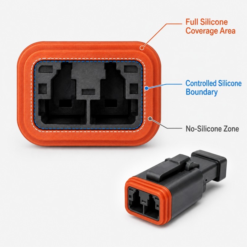
A useful engineering drawing should separate the product into three areas.
1. Full Silicone Coverage Zone
This is the area that should be completely covered by LSR.
Examples include:
• Waterproof sealing areas
• Protective encapsulation areas
• Bonding zones
• Mechanical-locking regions
• Strain-relief sections
• Insulation areas
2. Controlled Silicone Boundary Zone
This is the transition where the silicone is designed to stop.
The drawing should define the boundary position and its acceptable tolerance relative to a stable datum.
This region is important because an unstable silicone edge can expose too much substrate on one part and cover a functional area on another.
3. No-Silicone Zone
This area must remain exposed and functional.
The drawing should identify the exact protected area instead of relying only on product renderings or color differences.
For FPC applications, the same three-zone logic is especially useful when protecting gold fingers and contact pads.
How Should the No-Silicone Boundary Be Dimensioned?
The silicone boundary should be dimensioned from a stable and repeatable feature.
Avoid locating a critical boundary from:
• An irregular trimmed edge
• A flexible unsupported edge
• A cosmetic contour with large variation
• A warped plastic wall
• An uncontrolled adhesive boundary
Better datums may include:
• Precision locating holes
• Molded datum surfaces
• Metal reference features
• Connector reference faces
• FPC stiffener features
• Controlled insert edges
• Assembly datums
The drawing should define, where relevant:
• Required exposed length
• Required exposed width
• Silicone boundary position
• Boundary tolerance
• Distance from silicone to the active functional area
• No-flash requirement
• Datum location
• Final assembly clearance
The goal is to make the silicone coverage measurable rather than subjective.
A statement such as “keep the connector clean” is not enough for precision tooling.
Why Is Mold Shut-Off Critical Around a No-Silicone Zone?
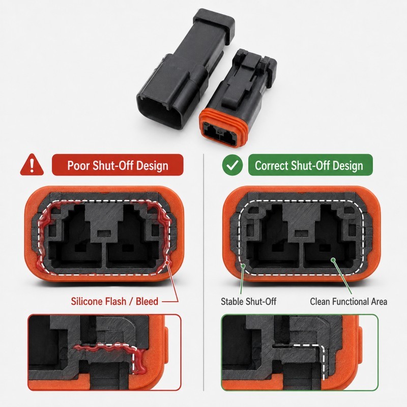
The mold shut-off is the contact region that prevents uncured silicone from entering the protected area.
A reliable shut-off should contact a stable and repeatable insert surface.
High-risk conditions include:
• Narrow shut-off contact
• Flexible unsupported insert surfaces
• Plastic parting lines
• Stiffener steps
• Irregular FPC edges
• Curved surfaces
• Burrs
• Textured surfaces
• Plating steps
• Warped plastic walls
• Contaminated mold contact areas
If the shut-off opens during injection, a very thin silicone film may enter the protected region.
That film can be enough to interfere with electrical contact, connector mating, screw engagement or final assembly even when it is difficult to see visually.
The shut-off structure should therefore be designed for the realistic insert-tolerance range, not only the nominal CAD geometry.
How Do Insert Position and Tolerance Affect the Protected Area?
A correctly designed mold can still produce an incorrect silicone boundary when the insert moves.
Possible movement includes:
• Sliding
• Tilting
• Rotation
• Bowing
• FPC lifting
• Cable movement
• Terminal displacement
• Incorrect manual loading
When the insert moves, the no-silicone zone moves relative to the mold shut-off.
The result may be:
• Silicone covering one side of a contact
• Uneven exposed terminal length
• Flash around an opening
• Different silicone boundaries between samples
• Assembly interference
• Electrical failure
Locating and support features should therefore be positioned close to the critical protected area whenever the structure permits.
For FPC-specific projects, review how to protect FPC gold fingers and contact pads during LSR overmolding.
For metal terminals and inserts, also review metal insert preparation before LSR overmolding, especially when part of the metal must remain electrically or mechanically exposed.
No-Silicone Zone DFM Checklist
DFM Item | What Engineers Should Confirm | Main Risk |
Functional area | Exact exposed surface is defined | Silicone covers a required feature |
Coverage map | Full coverage, boundary and no-silicone zones are separated | Drawing is ambiguous |
Datum | Boundary is measured from a stable reference | Exposure varies between parts |
| Boundary tolerance | Allowed silicone termination variation is defined | Assembly or contact interference |
Insert support | Protected area cannot lift or move | Shut-off gap opens |
Mold shut-off | Stable contact border is available | Thin silicone film or flash |
Insert tolerance | Thickness, flatness and position are reviewed | Shut-off becomes unstable |
| Parting line | Kept away from protected areas where possible | Flash crosses functional area |
| Gate direction | Flow does not push the insert | Boundary shift |
| Inspection | Optical, dimensional or functional method is defined | Thin film is missed |
The silicone mold design and tooling review should confirm the coverage map, no-silicone boundary, insert datum, support, shut-off, parting line, gate and inspection method before mold steel is finalized.
How Should No-Silicone Zones Be Validated?
Protected functional areas should be inspected using methods that match their actual function.
1. Visual and Optical Inspection
Check for silicone film, flash, boundary shift, surface damage, contamination and incorrect coverage.
Transparent silicone film can sometimes be difficult to detect under ordinary lighting, so controlled illumination or optical inspection may be useful for critical areas.
2. Dimensional Inspection
Measure:
• Exposed terminal length
• Hole diameter
• Silicone-to-contact distance
• Boundary position
• Assembly clearance
• Insert position
3. Functional Gauging
Use actual mating components or suitable gauges where possible.
Examples include:
• Connector mating tests
• Pin or plug gauges
• Screw engagement checks
• Assembly fixtures
• ZIF connector insertion
4. Electrical Testing
For terminals, FPC pads and conductive contacts, dimensional inspection alone may not confirm function.
Where appropriate, evaluate continuity, contact performance or final electrical function.
5. Cross-Section Inspection
Selected samples can be sectioned to evaluate hidden silicone intrusion, insert position, shut-off boundary, local silicone thickness and voids.
6. Pilot-Production Validation
Do not approve the no-silicone boundary based only on one good sample.
Multiple cavities, consecutive cycles and realistic incoming insert variation should be checked before mass-production approval.
How SiliconePlus Supports No-Silicone Zone DFM
SiliconePlus supports precision LSR overmolding projects involving plastic, metal, FPC, cable, connectors and electronic inserts.
Project support can include:
• Silicone coverage-map review
• Functional no-silicone-zone definition
• Insert datum and tolerance review
• Mold shut-off design
• FPC and terminal protection review
• Insert positioning and support design
• Gate and parting-line review
• Precision mold development
• LSR injection molding
• Optical and dimensional inspection
• Functional and pilot-production validation
For precision projects, the protected area, allowed boundary variation and inspection standard should be agreed before tooling rather than decided after the first samples are molded.
FAQ
Is a No-Silicone Zone the Same as a Cosmetic Area?
No. A no-silicone zone is normally defined because the underlying surface has a functional requirement such as electrical contact, assembly, fastening, sensing or fluid passage.
Can Silicone Be Trimmed from a Functional Area After Molding?
Secondary trimming may be possible in some non-critical structures, but precision electrical, sealing and assembly areas should not depend on uncontrolled manual trimming.
Why Does Silicone Cover Only One Side of a Terminal?
Possible causes include insert shift, tilt, dimensional variation, uneven support or an unstable mold shut-off.
Should the Mold Press Directly on Electrical Contacts?
Where possible, the shut-off should use a stable surrounding surface rather than damaging an active contact area.
How Can a Transparent Silicone Film Be Detected?
Controlled lighting, optical inspection, magnification and functional testing may be required when a very thin film is difficult to see.
Should No-Silicone Zones Be Defined Before Tooling?
Yes. The boundary affects mold shut-off, insert positioning, parting line, gate strategy and inspection, so it should be part of the DFM review.
Conclusion
A no-silicone zone should be treated as a precision functional feature rather than an empty area on the drawing.
Reliable control requires coordinated management of:
• Silicone coverage
• Stable datums
• Boundary tolerance
• Insert positioning
• Insert support
• Mold shut-off
• Parting line
• Gate direction
• Insert variation
• Inspection
The most important requirement is to clearly define where silicone must stop and how that boundary will remain repeatable during mass production.