Why Does LSR Overmolding Block Holes, Contact Pads, and Connector Openings?
Introduction
A custom LSR overmolded component may require silicone to cover one area while keeping another area completely exposed.
The silicone may need to form a waterproof sealing lip around a connector while leaving the electrical contacts open. It may need to protect an FPC circuit while keeping contact pads and test points uncovered. It may need to wrap around a metal insert without filling the screw hole, locating hole, thread, terminal or sensor window.
This sounds simple on a drawing. In production, it can become one of the most difficult parts of precision liquid silicone injection molding and overmolding.
Liquid silicone rubber can enter very small gaps. This makes it suitable for thin sealing structures and detailed geometries, but it also increases the risk of silicone entering areas that must remain open. Dow’s LSR processing guide notes that the material’s relatively low viscosity makes mold sealing, parting-line design and vent dimensions particularly sensitive to flash.
A small insert movement, mold gap or tolerance change can result in:
- A blind hole partially filled with silicone
- A screw hole becoming too small
- An electrical contact pad being covered
- A connector opening becoming obstructed
- Silicone flash around a terminal
- A test point becoming inaccessible
- A sensor window being contaminated
- A mating surface failing assembly
- A waterproof interface becoming dimensionally unstable
For engineers, purchasing teams and OEM buyers, the key question is not only whether the first sample looks correct.
The more important question is:
Can every functional opening remain clean, open and dimensionally stable during repeatable mass production?
Answer Excerpt
LSR overmolding can block holes, contact pads and connector openings when liquid silicone enters a gap between the mold and the insert.
The main causes include insufficient mold shutoff, insert movement, unstable insert dimensions, plastic deformation, incorrect parting-line location, excessive injection volume, unsuitable pressure, poor venting, damaged mold surfaces and tolerance stack-up.
Preventing blockage requires the functional areas to be defined before tooling. The mold must seal accurately around holes, pads, terminals and openings, while fixtures must hold the insert in a repeatable position.
Critical exposed areas should be validated through dimensional inspection, optical inspection, electrical testing, assembly testing and pilot production before mass production.
1. What Is a Blocked Functional Area in LSR Overmolding?
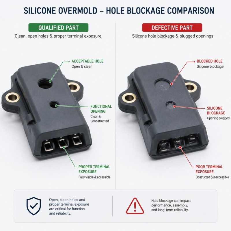
A blocked functional area is any location that should remain open, exposed or dimensionally controlled but becomes partially or completely covered by silicone.
Common examples include:
- Blind holes
- Through-holes
- Screw holes
- Threaded inserts
- Locating holes
- Connector openings
- Electrical terminals
- Metal contacts
- FPC contact pads
- FPC test points
- Sensor windows
- Speaker or microphone openings
- Type-C interfaces
- SIM-card tray areas
- Cable passages
- Fluid channels
- Assembly slots
- Button interfaces
- Mating surfaces
The defect does not always mean the entire opening is completely filled.
A thin silicone film may be enough to cause:
- Electrical contact failure
- Assembly interference
- Unstable screw engagement
- Incorrect positioning
- Reduced airflow
- Fluid-flow restriction
- Sensor-reading errors
- Waterproof-test variation
- Additional manual trimming
- Customer rejection
For precision electronic components, even a very thin flash membrane over a contact or opening may make the product unusable.
2. Why Can LSR Enter Such Small Gaps?
Liquid silicone rubber has high flow capability before curing.
During injection, the material flows through the runner and cavity around the insert. As it enters the heated mold, it begins to cure, but there is a period when the material can still flow into very small clearances.
If the gap between the mold and insert is not controlled, silicone can enter that gap and form flash or a thin blocking film.
Risk areas commonly include:
- The edge of a plastic opening
- The side of a metal terminal
- The surface around an FPC pad
- The boundary between two mold inserts
- The mold parting line
- A core pin around a hole
- A damaged or worn shutoff surface
- An insert with unstable thickness
- A flexible component that is not fully supported
LSR mold design therefore requires a careful balance.
The mold must allow air to escape, but it must not create a clearance large enough for silicone to form unwanted flash. Official LSR processing guidance emphasizes that low-viscosity material can be driven into very small gaps and that vent and parting-line dimensions must be carefully controlled.
3. Insufficient Mold Shutoff Is a Primary Cause
A mold shutoff is the area where two mold surfaces—or a mold surface and an insert—meet tightly enough to prevent silicone from entering a protected area.
For example, if a plastic connector has an opening that must remain free of silicone, the mold may use a precisely machined core or shutoff surface around that opening.
If the shutoff does not seal correctly, silicone may enter and create:
Shutoff performance should be evaluated together with flash and tolerance control before mold approval.
- Edge flash
- A thin silicone membrane
- Partial blockage
- Complete filling
- Unstable opening dimensions
- Damage during secondary trimming
Shutoff performance can be affected by:
- Mold-machining accuracy
- Insert dimensional tolerance
- Insert flatness
- Core-pin size
- Shutoff contact area
- Mold alignment
- Surface wear
- Contamination
- Clamping stability
- Thermal expansion
- Previous mold repair
A shutoff that works on one insert may fail when the next insert is slightly smaller, warped or positioned differently.
For this reason, mold shutoff must be designed for the real insert-tolerance range rather than only the nominal CAD dimension.
4. Poor Insert Positioning Changes the Protected Area
The mold may be designed correctly, but the functional area can still become blocked if the insert moves.
A stable insert positioning method is therefore essential for controlling silicone coverage and exposed functional zones.
Possible insert movement includes:
- Horizontal shift
- Vertical shift
- Rotation
- Tilting
- Bowing
- Floating under injection pressure
- FPC stretching
- Cable movement
- Terminal movement
- Incorrect manual loading
When the insert shifts, the mold shutoff may no longer align with the hole, pad or terminal.
The result may be:
- Silicone covering one side of a contact pad
- Uneven silicone around a connector opening
- A screw hole becoming eccentric
- A locating hole becoming too small
- A sealing lip moving toward the functional area
- Exposed substrate on the opposite side
Your existing insert-positioning article already explains that positioning error can produce overflow into functional zones, misaligned sealing lips and blocked assembly areas.
For repeatable production, insert positioning should not depend only on an operator placing the part “approximately” in the mold.
The design may require:
- Locating pins
- Datum surfaces
- Vacuum holding
- Mechanical clamps
- Nest fixtures
- Spring-loaded supports
- Magnetic positioning
- FPC tension control
- Cable clamps
- Vision inspection
- Poka-yoke loading orientation
5. Insert Tolerances Affect Mold Sealing
Overmolding quality depends on the insert as well as the silicone mold.
The insert may be produced by:
- Plastic injection molding
- Metal stamping
- CNC machining
- Die casting
- FPC fabrication
- Cable assembly
- Connector assembly
- Pre-molding
Each process introduces dimensional variation.
Important insert tolerances may include:
- Hole diameter
- Wall thickness
- Flatness
- Position of the hole
- Terminal height
- FPC thickness
- Connector width
- Insert length
- Edge radius
- Warpage
- Plating thickness
If the mold shutoff is designed around a nominal 3.00 mm hole but actual inserts vary significantly, the seal around the hole may not remain stable.
One insert may fit correctly. Another may leave a gap that allows silicone to enter.
The supplier should review:
- Drawing tolerances
- Actual insert measurement data
- Different insert batches
- Maximum and minimum material conditions
- Supplier-to-supplier variation
- Storage-related deformation
- Incoming inspection requirements
For customer-supplied inserts, several actual production samples should be measured before final mold design.
6. Excessive Injection Volume or Pressure Can Force Silicone Into Gaps
Even a well-designed shutoff can become unstable if the molding process creates excessive cavity pressure.
Possible contributing factors include:
- Too much injection volume
- Excessive holding pressure
- Incorrect injection speed
- Unstable machine dosing
- Material expansion inside the heated mold
- Unbalanced cavity filling
- Poor gate location
- Blocked venting
- Excessive clamping variation
When the cavity is overfilled, liquid silicone may be forced into small clearances around holes, terminals and parting lines.
Dow’s LSR processing guidance describes how cavity pressure rises as the material heats and expands before vulcanization, which can push uncured material into small gaps.
The process should fill the intended cavity completely without using excessive pressure to compensate for:
- Poor venting
- Incorrect gate design
- Insufficient runner balance
- Insert misalignment
- Incorrect material temperature
- Mold contamination
A stable process window should be established during mold trials and confirmed again during pilot production.
7. Poor Venting Can Indirectly Increase Blockage Risk
Venting is needed to allow trapped air to escape while silicone fills the cavity.
If air cannot escape, the process may produce:
- Short shots
- Incomplete filling
- Air traps
- Burn-like marks
- Weak bonding areas
- Bubbles
- Unstable flow fronts
Operators may try to solve incomplete filling by increasing pressure or injection volume.
This can force more silicone into the gaps around protected holes or contact areas.
Poor venting can therefore create two problems at the same time:
- Incomplete filling in one area
- Excessive flash or blockage in another area
The correct solution is not simply increasing pressure.
Gate location, flow direction, mold venting, insert geometry and cavity balance should be reviewed together. Your existing mold-venting article explains that inserts can divide a cavity into small spaces where air becomes trapped and that venting must allow air release without producing excessive flash.
8. Parting-Line Location Can Cross a Critical Opening
The mold parting line is where the mold separates.
If the parting line crosses a functional opening, contact pad, sealing surface or connector interface, the risk of flash increases.
Critical areas that should be reviewed include:
- Screw-hole edges
- Mating connector surfaces
- Electrical terminals
- Sensor windows
- Button-contact areas
- Fluid channels
- Sealing lips
- FPC pads
- Cosmetic Class-A surfaces
A parting line may be technically possible but still be a poor choice for product function.
During DFM, engineers should ask:
- Will flash affect assembly?
- Can the area be inspected?
- Can secondary trimming damage the insert?
- Is the parting line close to a waterproof path?
- Will the line cross a metal contact?
- Will repeated mold wear increase the risk?
- Can the mold be redesigned to move the line?
The parting-line position should be confirmed before tooling, because changing it after mold completion may require major mold modification.
9. Plastic Insert Deformation Can Open a Leakage Gap
Silicone over plastic projects require the plastic insert to remain stable under mold temperature, pressure and assembly conditions.
Plastic inserts are exposed to heat and pressure during LSR overmolding.
If the plastic structure is thin or insufficiently supported, it may:
- Warp
- Bow
- Twist
- Shrink
- Move away from the shutoff
- Lose flatness
- Change hole dimensions
A small amount of deformation can create a gap between the plastic and mold core.
Silicone may then flow into the opening or around the protected area.
This is especially important for:
- Thin connector housings
- Battery-cover structures
- Small sensor frames
- Wearable housings
- Type-C interface components
- SIM-card tray structures
- Thin plastic rings
- Long narrow inserts
The plastic grade, heat resistance, wall thickness, residual molding stress, support structure and insert temperature should be reviewed before mold development.
The process must cure the silicone without causing unacceptable plastic movement.
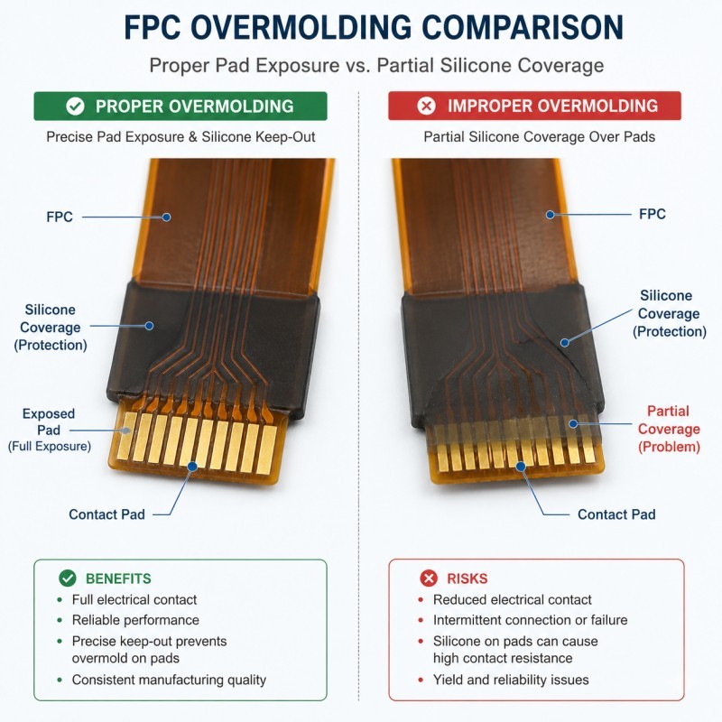
10. FPC Contact Pads Require Dedicated Protection
FPC silicone overmolding has additional risks because the flexible circuit is thin, light and easy to move.
The silicone may need to cover:
- Copper traces
- Solder joints
- Sensor areas
- Waterproof edges
- Reinforcement areas
At the same time, it may need to leave these areas exposed:
- Contact pads
- Test points
- Connector fingers
- Grounding areas
- Optical windows
- Component surfaces
- Bending zones
If the FPC shifts, stretches or bows inside the mold, the silicone coverage boundary may move.
Your existing FPC article identifies blocked contact pads, FPC displacement and silicone flash as key defects that can affect electrical function and assembly.
FPC protection may require:
- Precise locating holes
- Vacuum holding
- Flat support
- Controlled tension
- Stiffener positioning
- Protective core inserts
- Clearly defined silicone boundary
- Camera inspection before mold closing
- Electrical testing after molding
The drawing should clearly identify which areas must be fully covered, partially covered and completely exposed.
11. Metal Holes, Threads, Pins, and Terminals Need Accurate Sealing
Silicone over metal projects may require the mold to protect threads, pins, terminals and mounting holes while maintaining reliable bonding around the surrounding area.
Silicone over metal parts may include:
- Threaded inserts
- Metal pins
- Connector terminals
- Stainless-steel plates
- Aluminum housings
- Copper contacts
- Sensor probes
- Screw bosses
- Mounting holes
The mold may need to seal directly against the metal surface.
Risks include:
- Silicone filling the thread
- Flash around the terminal
- Hole-diameter reduction
- Silicone covering a contact surface
- Insert movement
- Plating damage
- Oil contamination affecting bonding
- Metal burrs damaging the mold shutoff
Metal components should be inspected for:
- Burrs
- Oil
- Oxidation
- Plating thickness
- Flatness
- Hole tolerance
- Edge condition
- Position accuracy
If the metal edge is rough or inconsistent, it may prevent the shutoff from sealing and damage the mold over repeated cycles.
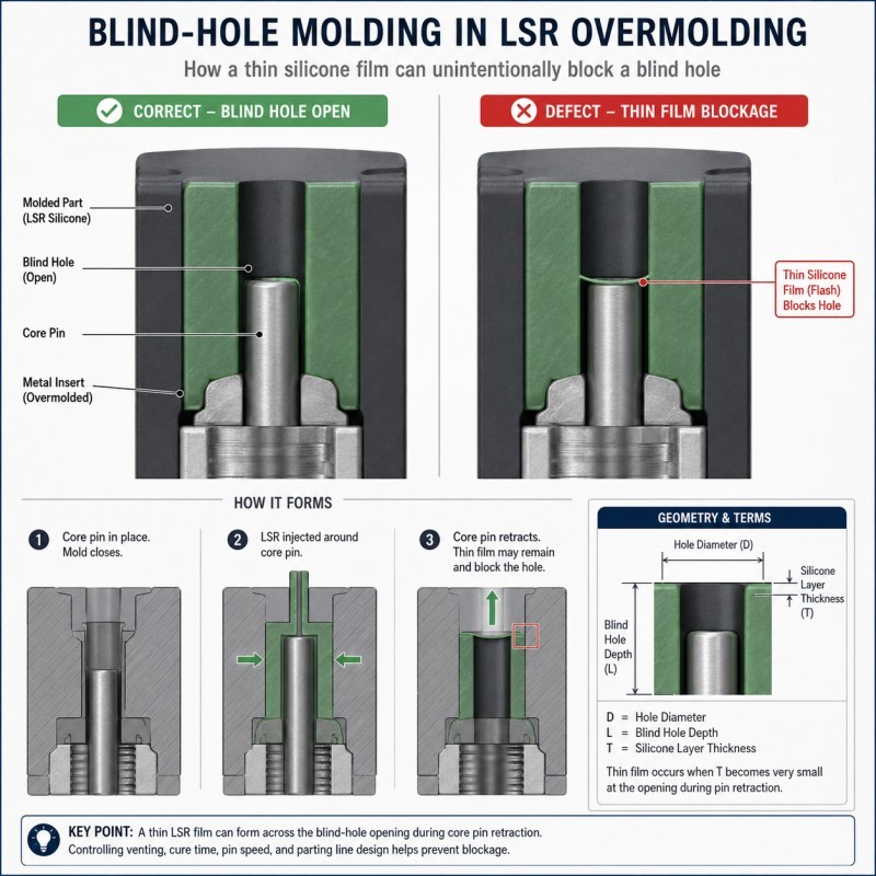
12. Blind Holes Are More Difficult Than Open Through-Holes
A blind hole does not pass completely through the insert.
This creates additional molding challenges because:
- Air may become trapped
- The core pin has limited support
- The hole depth may vary
- Silicone may enter around the core
- Demolding may be more difficult
- The protected surface may be hard to inspect
- Secondary trimming may be impossible
For a blind hole, the tooling design may require:
- A precision core pin
- Defined shutoff length
- Stable support
- Controlled venting
- Suitable draft
- Correct core surface finish
- Insert depth control
- Optical or pin-gauge inspection
The goal is not only to form the hole once during sampling.
The mold must repeatedly form the hole without:
- Silicone membranes
- Partial filling
- Flash rings
- Core-pin wear
- Dimensional drift
- Damage during demolding
SiliconePlus currently lists blind-area and long-tube molding among its liquid silicone injection capabilities, emphasizing the role of specialized mold structures.
13. Can Secondary Trimming Solve Blocked Holes?
Secondary trimming may remove some visible flash, but it is not the preferred solution for critical functional areas.
Manual trimming can introduce:
- Inconsistent hole dimensions
- Scratches
- Damaged terminals
- Cut sealing lips
- Contamination
- Remaining silicone film
- High labor cost
- Unstable production capacity
- Difficulty inspecting internal holes
For electrical contact pads and small connector openings, manual trimming may be especially risky.
A thin silicone film can remain even after the operator believes the opening is clean.
The better approach is to prevent the silicone from entering the area through:
- Correct shutoff design
- Stable insert positioning
- Controlled tolerances
- Suitable process parameters
- Preventive mold maintenance
Secondary trimming should not be used to compensate for an unstable mold design.
14. Why Does the Sample Pass but Mass Production Starts Blocking Holes?
Initial samples are often produced under close engineering supervision.
During sampling:
- Inserts may be selected carefully
- Mold surfaces are new
- The machine is adjusted slowly
- Each insert is loaded manually
- Engineers inspect every part
- Production time is short
Mass production introduces additional variation:
- Different insert batches
- Multiple operators
- Longer molding cycles
- Mold heating over time
- Shutoff wear
- Core-pin wear
- Material-batch changes
- Cavity-to-cavity differences
- Faster loading
- Equipment variation
- Contamination buildup
A design with very little process margin may pass 20 samples but fail after thousands of cycles.
Pilot production should therefore evaluate:
- All mold cavities
- Multiple insert batches
- Long continuous production
- Different operators
- Hole and pad dimensions
- Flash levels
- Functional testing
- Mold-cleaning intervals
- Tool-wear risk
The objective is not a successful first mold trial.
The objective is a repeatable manufacturing process.
15. How Should Functional Areas Be Defined on the Drawing?
The drawing should not only show the silicone outline.
It should clearly identify:
- Silicone coverage zone
- No-silicone zone
- Critical shutoff boundary
- Contact-pad area
- Hole diameter
- Hole depth
- Thread protection
- Terminal exposure length
- Sensor-window area
- Test-point area
- Maximum acceptable flash
- Minimum electrical clearance
- Assembly interface
- Inspection method
Useful drawing notes may include:
- No silicone permitted
- Keep contact area fully exposed
- Maximum flash allowed
- Pin gauge must pass
- Electrical contact resistance must meet requirement
- No silicone membrane
- Optical surface must remain clear
- Thread must remain functional
General statements such as “keep hole clean” are not always enough.
The drawing should define a measurable acceptance requirement.
16. A Practical Failure-Analysis Sequence
When holes, contact pads or connector openings become blocked, use a controlled investigation.
Recommended sequence:
- Identify the exact blocked location.
- Separate complete blockage, partial blockage and edge flash.
- Compare passing and failing samples.
- Check which mold cavity produced the defect.
- Measure the insert and protected opening.
- Check insert position inside the molded part.
- Inspect the mold shutoff and core pin.
- Check for mold wear, damage or contamination.
- Review insert flatness and deformation.
- Review injection volume, speed and pressure.
- Check venting and fill balance.
- Review mold temperature and continuous-run conditions.
- Compare different insert batches.
- Confirm whether the defect appears after a certain production quantity.
- Inspect the loading fixture and operator method.
- Repeat production after changing one controlled variable.
Do not change the insert fixture, injection pressure, venting and shutoff at the same time.
Changing one variable at a time makes it easier to identify the root cause.
17. What Should Be Validated Before Mass Production?
Before approving an LSR overmolded component, buyers and manufacturers should confirm:
- Final insert drawing
- Actual insert measurement
- Insert material
- Hole and pad tolerances
- Silicone coverage boundary
- No-silicone areas
- Mold shutoff structure
- Core-pin dimensions
- Insert positioning method
- Parting-line location
- Venting location
- Gate location
- Injection-process window
- Maximum acceptable flash
- Hole inspection method
- Electrical-test method
- Assembly-test method
- Optical-inspection standard
- Cavity-to-cavity consistency
- Pilot-production quantity
- Mold-maintenance plan
- Traceability requirements
For critical openings, inspection may include:
- Pin gauges
- Plug gauges
- Optical measurement
- Vision inspection
- Electrical continuity testing
- Contact-resistance testing
- Functional assembly
- Leak testing
- Thread inspection
The inspection method should match the function of the opening.
How SiliconePlus Supports Functional-Area Protection in LSR Overmolding
SiliconePlus provides custom liquid silicone injection molding and silicone overmolding services for precision components used in automotive electronics, 3C electronics, medical devices, sensors, wearable products, beauty devices and industrial equipment.
Our capabilities include:
- DFM and drawing review
- Liquid silicone injection molding
- Silicone over plastic
- Silicone over metal
- FPC silicone overmolding
- Precision insert positioning
- Blind-hole and long-tube molding
- Functional-area shutoff design
- Waterproof sealing structures
- Custom mold development
- Mold-flow and venting review
- Sample and pilot production
- Optical and dimensional inspection
- OEM/ODM mass production
With more than 25 years of silicone manufacturing experience, our team supports custom projects from early structural review and mold development to sampling, testing and repeatable production.
For projects containing holes, terminals, pads or connector openings, our engineering team reviews:
- Which areas require silicone coverage
- Which areas must remain exposed
- How the insert will be positioned
- How the mold will seal around the opening
- How insert tolerances affect shutoff
- How the opening will be inspected
- How production consistency will be validated
The objective is not only to produce a visually acceptable sample.
The objective is to keep every functional area clean and stable throughout mass production.
What Information Should Buyers Send for Evaluation?
To evaluate a project accurately, buyers should provide:
- 2D drawing
- 3D file
- Insert drawing
- Product or sample photos
- Silicone coverage area
- No-silicone area
- Hole diameter and depth
- Contact-pad location
- Terminal exposure requirement
- Substrate material
- Silicone material and hardness
- Waterproof requirement
- Electrical requirement
- Assembly requirement
- Critical tolerances
- Inspection standard
- Known blockage defect
- Estimated order quantity
- Target production schedule
If the project has already failed, provide photos of the blocked location, affected cavity, insert measurements, sample quantity and molding conditions.
Frequently Asked Questions
Why does LSR enter a screw hole even when the mold has a core pin?
The silicone may enter if the core pin does not seal tightly against the insert, the insert shifts, the hole tolerance is unstable, the plastic deforms, or cavity pressure becomes too high.
Can a thin silicone film over a hole be accepted?
That depends on the product function. For electrical contacts, air passages, sensor windows, screw holes and assembly interfaces, even a thin membrane may cause failure and should normally be treated as a critical defect.
Why are FPC contact pads difficult to protect?
FPC is thin and flexible. It may shift, bow or stretch during loading and injection. The mold needs accurate positioning and support so that the silicone coverage boundary remains stable.
Can higher clamping force prevent all flash?
No. Clamping force alone cannot correct poor shutoff geometry, insert variation, damaged mold surfaces, excessive injection volume or unstable positioning.
Can blocked holes be cleaned manually after molding?
Some external flash may be trimmed, but manual cleaning is risky for small holes, terminals and contact pads. A stable mold and process should prevent blockage instead of depending on secondary trimming.
How can hole blockage be inspected?
Depending on the opening, inspection may use pin gauges, plug gauges, vision systems, optical measurement, electrical testing, assembly testing or airflow testing.
Why does blockage appear only after long production runs?
Long runs may introduce mold-temperature changes, shutoff wear, core-pin wear, contamination, operator variation or material buildup. Pilot production should evaluate continuous-run stability.
Conclusion
Blocked holes, covered contact pads and obstructed connector openings are not caused by one single molding parameter.
The defect may result from mold shutoff, insert positioning, insert tolerances, plastic deformation, injection pressure, filling volume, venting, parting-line location, core-pin wear or production variation.
Because LSR can flow into very small gaps, protected functional areas must be defined and controlled before mold development.
The most reliable approach is to review the insert and silicone structure together, design a precise shutoff, stabilize insert positioning, establish a repeatable process window and validate every critical opening during pilot production.
If you are developing a silicone overmolded connector, FPC component, sensor, metal insert or plastic housing with holes, pads or exposed functional areas, contact SiliconePlus and send us your drawings, insert material, silicone coverage area, exposed-area requirements, tolerances, testing standards and estimated quantity. Our team will review the project and provide practical manufacturing recommendations.