How Should Silicone Overmolded Connectors Be Designed for Waterproof Sealing?
Answer Excerpt
A silicone overmolded connector can provide stable waterproof sealing only when the insert, mold and final assembly are designed as one system. Reliable performance depends on accurate insert positioning, controlled plastic tolerances, stable mold shut-off, uniform silicone thickness, suitable bonding or mechanical retention, and correctly compressed sealing features. Waterproof requirements must be validated on the completed assembly under defined pressure, immersion time, temperature and environmental conditions—not judged only by the appearance of the molded part.
Silicone overmolding is widely used to integrate soft sealing features directly onto plastic connector housings, metal terminals, cable interfaces and electronic frames.
Compared with a separately assembled gasket, an overmolded seal can reduce part count, eliminate manual gasket placement and improve sealing repeatability. However, an overmolded connector does not automatically become waterproof simply because silicone surrounds the plastic insert.
Many connector leakage problems are caused by structural tolerances, insert movement, mold shut-off, insufficient compression or unstable bonding rather than by the silicone material itself.
For connector, sensor and electronic housing projects, custom automotive silicone solutions should be evaluated from DFM through tooling, molding, assembly and final leak testing.
What Is a Silicone Overmolded Connector?
A silicone overmolded connector is a multi-material component in which liquid silicone rubber or molded silicone is integrated with another substrate.
The substrate may include:
- Thermoplastic connector housing
- Metal terminal
- Cable jacket
- FPC
- Electronic sensor frame
- Rigid insert
- Pre-molded plastic component
The silicone may form:
- Peripheral sealing lip
- Cable strain relief
- Terminal sealing area
- Waterproof interface
- Soft-touch protection
- Vibration-damping section
- Dustproof cover
- Integrated gasket
The main advantage is that the silicone seal is created during molding rather than installed as a separate component.
This can improve assembly efficiency, but only when the interface geometry and molding process are stable.
Why Do Silicone Overmolded Connectors Leak?
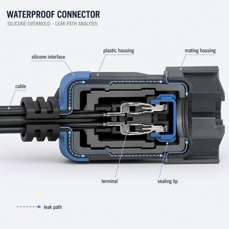
Connector leakage normally follows one or more continuous paths between the external environment and the protected electrical area.
Common leakage paths include:
- Between the silicone and plastic housing
- Around a metal terminal
- Along the cable jacket
- Through an underfilled silicone region
- Across a damaged sealing lip
- Through flash or a poorly controlled parting line
- Around a warped plastic insert
- Between the connector seal and mating component
A visually complete overmold does not prove that all of these paths are sealed.
The leak may only appear after:
- Connector assembly
- Cable bending
- Terminal insertion
- Thermal cycling
- Vibration
- Water immersion
- Pressure testing
- Long-term compression
- Chemical exposure
For this reason, engineers should define the complete sealing path before designing the mold.
1. Insert Positioning Must Be Stable During Injection
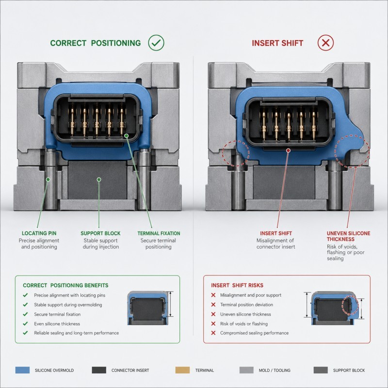
Insert movement is one of the most common causes of inconsistent connector overmolding.
During LSR injection, the plastic housing, terminal or cable insert is exposed to pressure and heat. If the insert is not fully supported, it may shift, lift, tilt or rotate inside the cavity.
Even a small displacement can cause:
- Uneven silicone thickness
- Exposed substrate
- Local short shot
- Excessive flash
- Misaligned sealing lip
- Reduced bonding area
- Terminal contamination
- Incorrect connector dimensions
Recommended positioning methods
Connector inserts may be positioned using:
- Defined datum surfaces
- Precision locating pins
- Terminal support blocks
- Housing shoulders
- Cavity nests
- Cable clamping features
- Vacuum assistance
- Controlled robotic placement
The positioning system should locate the insert without damaging the electrical contact area or creating permanent witness marks on critical surfaces.
For complicated inserts, the tool should support the component close to the injection region so that LSR pressure cannot deform unsupported sections.
To understand this issue in more detail, review how insert positioning affects custom LSR overmolding quality.
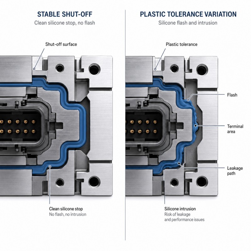
2. Mold Shut-Off Controls Flash and Leakage Paths
A mold shut-off is the contact area where the mold steel closes against the plastic, metal or cable insert to stop silicone flow.
Poor shut-off design can create:
- Silicone flash over terminal areas
- Blocked connector openings
- Uncontrolled sealing edges
- Thin silicone films
- Irregular parting lines
- Leakage paths between materials
- Insert damage caused by excessive clamping
The shut-off must seal against a controlled and repeatable insert surface.
If the plastic insert has excessive variation, the mold may not close consistently. A loose shut-off allows silicone to escape, while an excessively tight shut-off may crush or mark the insert.
Important shut-off considerations
Engineers should evaluate:
- Insert dimensional tolerance
- Plastic warpage
- Draft angle
- Shut-off width
- Shut-off angle
- Mold-steel wear
- Insert surface finish
- Parting-line location
- Expected production volume
- Maintenance access
Critical sealing edges should not rely on a narrow, unstable shut-off surface.
Where possible, the shut-off should be placed on a rigid plastic region with sufficient structural support.
3. Silicone Thickness Must Be Uniform and Manufacturable
Silicone thickness affects flow, curing, deformation and sealing performance.
If the silicone is too thin, the overmold may develop:
- Short shots
- Tearing
- Incomplete bonding
- Unstable seal lips
- Local flash sensitivity
- Damage during demolding
If the silicone is excessively thick, the part may experience:
- Longer curing time
- Trapped air
- Sink-like deformation
- Uneven shrinkage
- Higher material consumption
- Dimensional instability
A connector design should avoid sudden thickness changes wherever possible.
Good thickness transitions
Use:
- Smooth thickness transitions
- Rounded internal corners
- Continuous flow paths
- Stable sealing-lip roots
- Adequate silicone around mechanical locks
- Consistent material around the connector perimeter
Avoid:
- Extremely thin unsupported edges
- Abrupt thick-to-thin transitions
- Deep blind pockets
- Long narrow flow channels
- Sharp re-entrant corners
- Thick isolated silicone masses
The exact minimum thickness depends on part geometry, LSR grade, gate location and mold capability. It must be validated through DFM and mold trials rather than chosen from a universal number.
4. Chemical Bonding Alone May Not Be Sufficient
A silicone overmold may rely on:
- Self-bonding LSR
- Primer
- Plasma treatment
- Mechanical retention
- A combination of these methods
Chemical adhesion can improve interface sealing, but long-term connector performance should not depend only on a flat bonding surface when the part is exposed to peel loading, cable movement or thermal expansion.
Plastic and silicone have different mechanical and thermal behavior. Repeated temperature changes can gradually concentrate stress at the interface edge.
Mechanical retention features
Common retention structures include:
- Through-holes
- Slots
- Dovetail grooves
- Edge wraparound
- Interlocking channels
- Perforated ribs
- Undercut windows
- Silicone anchors
These features allow the cured silicone to lock physically into the substrate.
Mechanical retention is especially valuable when:
- The plastic is difficult to bond
- The connector will be pulled or bent
- The application experiences vibration
- The assembly undergoes thermal cycling
- Leakage would cause electrical failure
- Material grades may change in future production
Mechanical locks must still be designed for complete filling and venting. A deep retention groove that traps air may create a hidden void instead of improving reliability.
For material-selection guidance, refer to plastic with silicone overmolding.
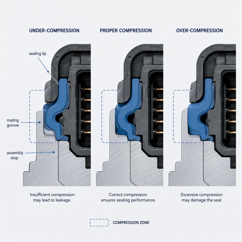
5. The Sealing Lip Must Have Controlled Compression
Many overmolded connectors seal against a mating housing, panel, cover or connector shell.
The sealing lip must be compressed enough to maintain continuous contact, but not so much that it becomes permanently deformed or difficult to assemble.
Too little compression may cause:
- Incomplete surface contact
- Leakage through tolerance gaps
- Poor sealing after vibration
- Sensitivity to housing warpage
- Inconsistent assembly results
Too much compression may cause:
- Excessive assembly force
- Seal rolling
- Seal cutting
- Permanent deformation
- Plastic housing distortion
- Reduced long-term recovery
Compression is affected by:
- Silicone hardness
- Lip height
- Lip width
- Groove depth
- Mating-part tolerance
- Housing flatness
- Assembly stop
- Surface finish
- Temperature
- Long-term storage
The compression ratio should be calculated using the worst-case tolerance condition, not only the nominal drawing dimensions.
A design that works at nominal dimensions may leak when the silicone lip is at its minimum size and the mating groove is at its maximum size.
6. Tolerance Stack-Up Must Be Reviewed Before Tooling
A connector may contain tolerances from:
- Plastic insert molding
- Terminal stamping
- Cable diameter
- LSR overmolding
- Mating housing
- Assembly fixture
- Connector locking mechanism
These tolerances accumulate.
If each part is evaluated separately, the final assembly may still fail.
Example tolerance risks
A plastic housing may be slightly undersized, while the silicone seal is also at its lower tolerance and the mating groove is at its upper tolerance. Each part may pass inspection individually, but the assembled seal may have insufficient compression.
The opposite condition may cause excessive compression and assembly difficulty.
A DFM review should therefore include:
- Minimum seal compression
- Maximum seal compression
- Insert-position tolerance
- Shut-off tolerance
- Final connector envelope
- Terminal location
- Mating-part dimensional range
- Assembly-stop position
Statistical process capability should also be considered for critical high-volume connector dimensions.
7. Gate Location Affects Insert Movement and Filling Balance
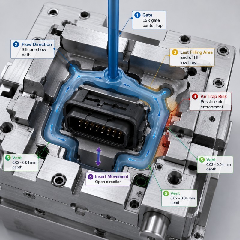
The gate introduces LSR into the mold cavity.
An unsuitable gate position may direct the material flow against a weak insert area, causing movement or deformation.
Poor gate selection can also create:
- Uneven filling
- Weld lines
- Air traps
- Local pressure concentration
- Incomplete retention-feature filling
- Visible gate marks
- Unbalanced silicone thickness
Gate design objectives
The gate should:
- Fill the sealing region evenly
- Avoid pushing the insert out of position
- Minimize trapped air
- Support stable cavity pressure
- Avoid critical cosmetic surfaces
- Avoid direct flow into terminal openings
- Permit reliable demolding
For multi-cavity tooling, the runner system must also provide balanced filling between cavities.
Cold-runner LSR tooling can improve material control, but mold temperature, gate size and filling sequence still need process validation.
8. Venting Is Critical for Waterproof Connector Quality
Air inside the cavity must escape as LSR fills the sealing geometry.
If the final fill location is not adequately vented, the trapped air may create:
- Short shot
- Burn-like marks
- Voids
- Weak bonding
- Bubbles
- Incomplete sealing lips
- Internal leakage paths
Retention holes, narrow grooves and terminal areas are common locations for trapped air.
Venting should be reviewed at:
- Final fill points
- Deep sealing grooves
- Mechanical-lock structures
- Terminal boundaries
- Cable interfaces
- Thin silicone lips
- Closed-end cavities
Vacuum-assisted molding may improve filling for complex parts, but it cannot replace correct gate and vent design.
The vent must release air without allowing unacceptable silicone flash.
9. Cable and Terminal Interfaces Require Separate Sealing Analysis
A connector may appear sealed around the external housing while still leaking along the terminal or cable interface.
Cable-related risks
- Cable-jacket diameter variation
- Contamination on the jacket
- Poor silicone-to-jacket adhesion
- Cable movement during injection
- Cable ovality
- Excessive bending near the overmold
- Insufficient strain relief
- Capillary leakage along conductor interfaces
Terminal-related risks
- Terminal movement
- Silicone entering contact areas
- Inadequate terminal support
- Leakage along stamped-metal edges
- Surface contamination
- Insufficient encapsulation length
- Damage during terminal insertion
The sealing concept must distinguish between:
- Housing-to-silicone sealing
- Terminal-to-silicone sealing
- Cable-to-silicone sealing
- Final connector-to-mating-part sealing
Each interface may need a different structural solution.
10. Plastic Insert Warpage Can Destroy the Seal
Plastic connector housings may warp because of:
- Residual molding stress
- Glass-fiber orientation
- Uneven wall thickness
- Storage temperature
- Moisture absorption
- Mold temperature
- Overmolding pressure
- Repeated heating
A warped insert can create uneven silicone thickness and unstable shut-off.
In some projects, the plastic insert passes incoming inspection but changes shape after exposure to the heated LSR mold.
Recommended controls
- Review plastic resin heat resistance
- Check residual stress from plastic molding
- Control insert storage
- Support thin walls in the LSR mold
- Verify flatness before and after overmolding
- Run repeated-cycle dimensional studies
- Avoid unnecessary insert heating time
- Validate glass-filled resin orientation
Plastic flatness and datum stability should be treated as critical inputs to the silicone process.
What Does a Reliable Waterproof Connector Structure Look Like?
A robust connector sealing design normally includes several layers of protection.
Primary sealing feature
This may be:
- Compressed sealing lip
- Radial seal
- Axial gasket
- Cable encapsulation
- Terminal barrier
- Overmolded perimeter seal
Secondary interface protection
This may include:
- Chemical adhesion
- Mechanical retention
- Edge wraparound
- Extended sealing path
- Water-blocking rib
Structural control
The design should also include:
- Stable insert datum
- Controlled assembly stop
- Supported plastic walls
- Predictable shut-off surface
- Tolerance-controlled mating geometry
A reliable design should not depend on one fragile edge or one uncontrolled bonding surface.
Recommended DFM Process Before Tooling
Step 1: Define the complete assembly
Provide:
- Connector 2D and 3D drawings
- Mating-part drawing
- Terminal drawing
- Cable specification
- Plastic resin grade
- LSR hardness
- Required waterproof performance
- Operating temperature
- Expected production quantity
- Environmental test requirements
Step 2: Identify every possible leakage path
Mark the complete path from the external environment to the protected internal area.
Review:
- Plastic-to-silicone interface
- Terminal interface
- Cable interface
- Mating seal
- Parting line
- Assembly gaps
Step 3: Complete tolerance analysis
Calculate minimum and maximum seal compression using the full tolerance stack.
Step 4: Review molding feasibility
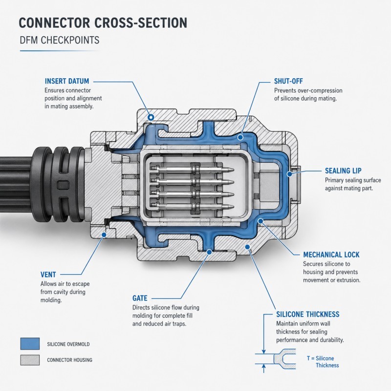
The silicone mold design and tooling review should cover:
- Insert positioning
- Mold shut-off
- Gate
- Vent
- Silicone thickness
- Mechanical lock
- Demolding
- Critical dimensions
Step 5: Define the sample validation plan
Testing requirements should be agreed before tooling is completed.
This prevents disagreement after samples are produced.
DFM Checklist for Silicone Overmolded Connectors
| DFM item | Engineering question |
|---|---|
| Substrate material | Is the exact plastic, metal, cable or FPC grade confirmed? |
| Insert datum | Is there a stable and repeatable positioning reference? |
| Insert support | Can the insert resist injection pressure without moving? |
| Shut-off surface | Is the shut-off located on a rigid, controlled surface? |
| Silicone thickness | Is thickness continuous and manufacturable? |
| Bonding method | Is self-bonding LSR, primer, plasma or mechanical locking required? |
| Mechanical retention | Are holes, grooves or edge locks needed? |
| Sealing lip | Are lip geometry and hardness suitable for the mating part? |
| Compression | Are minimum and maximum compression calculated? |
| Gate location | Will filling pressure move or deform the insert? |
| Venting | Can air escape from all final-fill regions? |
| Terminal protection | Are electrical contact areas protected from silicone? |
| Cable sealing | Are jacket material and diameter tolerance controlled? |
| Plastic warpage | Will the insert remain stable at molding temperature? |
| Demolding | Will ejection damage the sealing lip or bonding edge? |
| Test method | Are pressure, water depth, time and temperature defined? |
| Traceability | Can plastic, silicone and process lots be traced? |
How Should Waterproof Connector Samples Be Tested?
A sample should not be approved only because it looks complete.
The validation plan should include both part-level and assembly-level testing.
1. Visual inspection
Inspect:
- Short shot
- Flash
- Bubbles
- Surface contamination
- Exposed insert
- Damaged seal lip
- Gate mark
- Parting-line condition
- Terminal contamination
2. Dimensional inspection
Measure:
- Seal-lip height
- Seal-lip width
- Connector envelope
- Terminal position
- Insert position
- Silicone thickness
- Mating dimensions
- Flatness
- Critical shut-off dimensions
Optical measuring equipment may be required for small sealing features.
3. Adhesion or pull testing
Apply force in the direction that represents actual product loading.
Record:
- Maximum force
- Displacement
- Failure position
- Adhesive failure
- Cohesive failure
- Plastic breakage
- Sample variation
A single pull value should not be treated as universal. Acceptance criteria must be based on the final application.
4. Air-leak testing
Air-leak testing can identify leakage without immersing sensitive electronics.
The test specification should define:
- Test pressure
- Stabilization time
- Test duration
- Allowed leakage rate
- Fixture sealing method
- Product temperature
The fixture must not accidentally seal the same interface being evaluated.
5. Water-immersion testing
Define:
- Water depth
- Test duration
- Water temperature
- Product orientation
- Whether pressure is applied
- Whether the connector is assembled
- Acceptance method
A statement such as “IP68 capable” is incomplete without defined test conditions.
The completed assembly—not only the loose silicone part—must be evaluated.
6. Thermal cycling
Thermal cycling can expose:
- Interface delamination
- Plastic warpage
- Seal-compression loss
- Edge lifting
- Leakage caused by material expansion differences
The connector should be leak-tested again after cycling.
7. Vibration and mechanical shock
Automotive and industrial connectors may experience continuous vibration.
Testing should evaluate:
- Terminal movement
- Cable movement
- Seal wear
- Interface cracking
- Connector-lock stability
- Leakage after vibration
8. Cable bending and pull testing
For cable overmolding, test:
- Pull force
- Repeated bending
- Bend radius
- Torsion
- Jacket separation
- Leakage after mechanical loading
The strain-relief geometry should prevent the bending load from concentrating directly at the sealed interface.
9. Assembly-cycle testing
Repeated mating and unmating may damage or displace the silicone seal.
Inspect:
- Seal rolling
- Cutting
- Abrasion
- Permanent deformation
- Increased insertion force
- Leakage after repeated cycles
Common Failure Symptoms and Likely Causes
| Failure symptom | Possible cause |
|---|---|
| Silicone flash enters connector opening | Loose shut-off, insert variation or mold wear |
| Seal lip is higher on one side | Insert movement or incorrect positioning |
| Leakage occurs only after assembly | Incorrect compression or mating-part tolerance |
| Leakage occurs after thermal cycling | Interface stress, plastic warpage or seal deformation |
| Cable can rotate inside overmold | Weak jacket adhesion or insufficient mechanical lock |
| Terminal area contains silicone | Poor terminal shut-off or inadequate support |
| Bubbles appear around retention holes | Trapped air or moisture |
| Silicone peels from plastic edge | Peel-loading geometry or incompatible material |
| Samples pass but production fails | Material, insert or process conditions are not controlled |
| Connector is difficult to assemble | Excessive seal compression or lip interference |
Typical Applications
Automotive connectors
- Battery-management-system connectors
- High-voltage connector seals
- Charging-port components
- Sensor connectors
- Wire-harness interfaces
- Motor and inverter connectors
Consumer electronics
- Waterproof charging ports
- Camera-module frames
- Smart-device connectors
- Wearable charging interfaces
- Speaker and microphone sealing structures
Medical electronic devices
- Sensor housings
- Respiratory-device connectors
- Monitoring-equipment interfaces
- Fluid-control electronic components
The complete material system and final application requirements must be reviewed before claiming medical suitability.
Industrial equipment
- Waterproof sensor connectors
- Outdoor control housings
- Cable-entry seals
- Electrical insulation assemblies
- Vibration-resistant connectors
How SiliconePlus Supports Waterproof Connector Overmolding
SiliconePlus supports connector overmolding projects from drawing review and DFM through tooling, sampling, testing and mass production.
Project support includes:
- Plastic, metal, cable and FPC insert review
- Silicone material and hardness selection
- Connector leakage-path analysis
- Insert-positioning design
- Shut-off and flash-control review
- Mechanical-retention design
- Seal-compression analysis
- Precision mold manufacturing
- LSR injection molding
- Dimensional inspection
- Bonding and pull testing
- Airtightness and waterproof testing
- Prototype-to-volume production support
SiliconePlus has 25 years of silicone manufacturing experience, a 6000㎡+ production base, more than 6000 developed silicone projects, in-house CNC and EDM mold-processing capability, LSR injection equipment and precision inspection resources.
Capability values such as tolerance and waterproof performance should always be evaluated according to the specific product structure, material combination and agreed test conditions.
FAQ
Can silicone overmolding make any connector waterproof?
No. Waterproof performance depends on the complete connector structure, mating part, seal compression, material interface and test conditions. Silicone alone cannot compensate for an unstable housing or incorrect seal geometry.
Is chemical bonding required for a waterproof connector?
Not always, but the interface must prevent a continuous leakage path. Self-bonding LSR, primer, plasma treatment and mechanical retention may be used individually or together.
Why does a connector pass the first leak test but fail after thermal cycling?
Plastic and silicone expand differently. Thermal cycling may cause insert warpage, interface stress, seal-compression change or edge delamination.
How much should a silicone connector seal be compressed?
There is no universal percentage for every connector. The required compression depends on hardness, lip geometry, groove dimensions, surface finish, tolerance and service life. Minimum and maximum compression must be calculated for the actual assembly.
What causes silicone flash around terminals?
Typical causes include weak shut-off, terminal variation, insert movement, mold wear and excessive local cavity pressure.
Should the connector be tested before or after assembly?
Both may be useful, but final waterproof approval should be based on the completed assembly under defined application conditions.
Can LSR be overmolded onto cable jackets?
Yes, but compatibility depends on the jacket material, surface condition, diameter tolerance and mechanical-retention design. Cable bending and pull testing are necessary.
What files are needed for connector DFM?
Provide connector and mating-part drawings, plastic resin information, terminal or cable specifications, LSR hardness, annual volume, assembly conditions and waterproof test requirements.
Conclusion
Reliable silicone overmolded connector sealing is created by the combined control of:
- Insert positioning
- Mold shut-off
- Silicone thickness
- Material bonding
- Mechanical retention
- Seal compression
- Tolerance stack-up
- Gate and venting
- Cable and terminal interfaces
- Environmental validation
The most important work should be completed before tooling.
A detailed DFM review allows engineers to identify leakage paths, calculate seal compression, control insert movement and define the correct test plan before the project enters mass production.
For a project-specific review, send your connector drawing, material information and waterproof requirements to the SiliconePlus engineering team.