How Should Wall Thickness Be Designed for LSR Overmolding?
Answer Excerpt
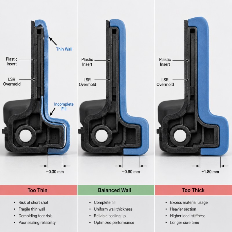
LSR overmolding wall thickness should be selected according to the complete product structure rather than one universal minimum value. Engineers should evaluate silicone hardness, flow length, sealing function, insert support, gate position, demolding and expected mechanical loading together. Thin sections may be difficult to fill or tear during demolding, while unnecessarily thick sections can increase material use, curing time and dimensional variation.
Wall thickness is one of the first structural details that should be reviewed before an LSR overmolding tool is manufactured.
A silicone overmold may contain sealing lips, protective walls, mechanical-locking zones, soft-touch surfaces, strain-relief sections and transition areas in the same component.
These areas do not always need the same thickness.
A sealing lip may need controlled flexibility, while the root around a plastic insert needs enough silicone to resist tearing. A thin cosmetic cover may need uniform filling, while a mechanical lock requires enough material around the anchor to transfer load.
This is why simply making every silicone section thicker does not automatically create a stronger or more reliable product.
For precision multi-material components, liquid silicone injection molding should be reviewed together with wall thickness, mold flow, insert support and the final functional requirements.
Why Does Wall Thickness Matter in LSR Overmolding?
Wall thickness affects how silicone flows, cures, deforms, seals and survives demolding.
Important effects include:
• Cavity filling
• Silicone flow resistance
• Air-trap risk
• Cure time
• Tear resistance
• Seal flexibility
• Compression behavior
• Demolding stability
• Material consumption
• Final dimensional consistency
The same LSR grade can behave very differently in a thin unsupported lip and a thick fully supported section.
Wall thickness must therefore be evaluated together with silicone hardness and geometry.
For example, increasing hardness may not solve a weak thin edge, and choosing a softer silicone may not solve an excessively thick and rigid sealing structure.
The objective is not to make the silicone as thin or as thick as possible.
The objective is to use enough material for stable molding and function without creating unnecessary mass or stiffness.
What Happens If the Silicone Wall Is Too Thin?
A thin silicone section may be desirable for flexibility or compact packaging, but the section still has to fill and demold consistently.
If the wall becomes too thin for the selected geometry and process, possible problems include:
• Short shots
• Missing edges
• Incomplete sealing lips
• Local tearing
• Uneven silicone thickness
• Weak bonding boundaries
• Difficult demolding
• Reduced sealing pressure
• High sensitivity to insert movement
• Greater cavity-to-cavity variation
Long thin flow paths are particularly difficult because the silicone must travel through a restricted section before the cavity is completely filled.
The problem becomes more serious when the thin area is located behind an insert, after a sudden flow split or near a poorly vented final-fill position.
A minimum wall thickness should therefore not be selected from a generic number alone.
It should be validated using the actual flow length, gate position, LSR grade, insert geometry and mold temperature.
For related filling risks, review why LSR overmolded parts develop short shots and incomplete edges.
What Happens If the Silicone Wall Is Too Thick?
More silicone does not automatically mean higher reliability.
An unnecessarily thick overmold may create:
• Longer curing time
• Higher silicone consumption
• Increased part weight
• More difficult dimensional control
• Larger local stiffness
• Uneven cooling after demolding
• Greater deformation around unsupported areas
• More difficult control of thick-to-thin transitions
A thick silicone section can also change the way the product feels or assembles.
For example, a thick sealing region may generate more assembly force than required. A thick cable strain-relief root may become too rigid and transfer bending stress directly to the cable exit.
When additional strength is required, engineers should first determine whether the problem should be solved by wall thickness, a support rib, mechanical retention, geometry or a different hardness.
Material should be added only where it provides a functional benefit.
Why Should Abrupt Wall-Thickness Changes Be Avoided?
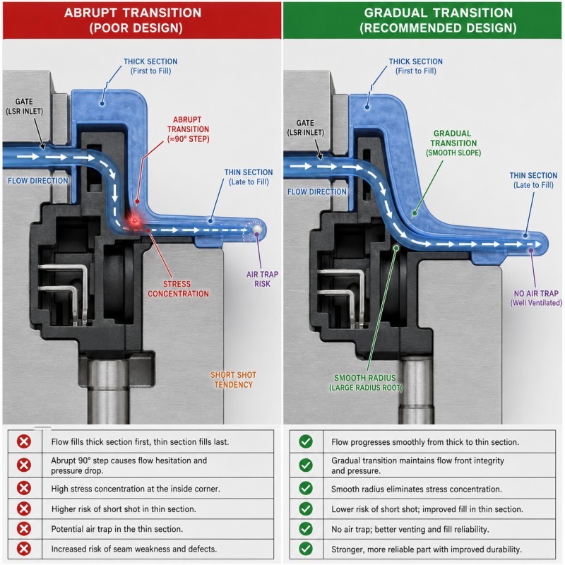
Abrupt thick-to-thin transitions can create both molding and mechanical problems.
During filling, silicone normally follows the lower-resistance flow path.
If one section suddenly becomes much thicker than the neighboring region, the thick section may fill first while the thin section receives material later.
This may cause:
• Uneven filling
• Flow imbalance
• Air traps
• Weld lines
• Short shots in thin features
• Local pressure differences
After molding, a sharp thickness transition may also become a stress-concentration area.
This is especially important near:
• Sealing-lip roots
• Insert edges
• Mechanical locks
• Cable exits
• Flexible hinges
• Button membranes
Where possible, use smooth radii, tapered transitions or gradual thickness changes instead of an abrupt 90-degree step.
The transition should still remain compatible with the intended mold opening and demolding direction.
LSR Wall Thickness DFM Checklist
| DFM Item | What Engineers Should Confirm | Main Risk |
Product function | Seal, protection, bending or soft touch is defined | Thickness does not match function |
Thin sections | Flow length and filling difficulty are reviewed | Short shot or tearing |
Thick sections | Extra thickness has a real structural purpose | Longer cure and excess stiffness |
Thickness transition | Smooth radius or taper is provided | Flow imbalance and stress concentration |
Silicone hardness | Hardness is reviewed together with geometry | Part becomes too soft or too rigid |
Insert support | Thin plastic or FPC cannot move under pressure | Uneven wall thickness |
Gate location | Silicone reaches thin areas predictably | Thin zones fill last |
| Venting | Air can escape from final-fill areas | Bubbles or incomplete filling |
| Demolding | Thin lips and transitions can release safely | Stretching or tearing |
The silicone mold design and tooling review should confirm wall thickness together with gate location, venting, insert support, parting line and demolding direction before mold steel is finalized.
How Should LSR Wall Thickness Be Validated?
Wall thickness should be approved using molded samples and the final product function rather than only the 3D model.
Recommended validation includes:
1. Cross-Section Inspection
Cut selected samples through thin areas, thick transitions and mechanical locks to confirm actual silicone distribution.
2. Dimensional Inspection
Measure critical wall thickness, sealing-lip geometry and silicone coverage boundaries.
3. Filling Inspection
Check thin edges, closed-end channels and final-fill areas for short shots or trapped air.
4. Demolding Inspection
Inspect thin lips and transitions for stretching, tearing or permanent deformation.
5. Assembly Test
Confirm that thick sections do not create excessive insertion or compression force.
6. Functional Testing
Evaluate sealing, bending, pull force, button movement or protection according to the product function.
7. Multi-Cavity Validation
Compare each mold cavity for wall-thickness and filling consistency.
8. Pilot Production
Run consecutive molding cycles to confirm that the design remains stable under normal production conditions.
The final design should be based on both molding feasibility and product performance.
How SiliconePlus Supports LSR Wall-Thickness DFM
SiliconePlus supports custom LSR overmolding projects from drawing and structural review through tooling, sampling, inspection and mass production.
Project support can include:
• Silicone wall-thickness review
• Thin-wall filling-risk analysis
• Thick-to-thin transition optimization
• Silicone hardness review
• Insert-positioning and support design
• Gate and venting analysis
• Mechanical-retention review
• Mold parting-line and demolding review
• Precision mold manufacturing
• LSR injection molding
• Cross-section and dimensional inspection
• Functional and pilot-production validation
SiliconePlus has 25 years of silicone manufacturing experience, more than 6,000 developed silicone projects, in-house mold-processing capability, liquid silicone injection equipment and precision inspection resources.
Specific wall thickness, tolerance, sealing performance and test requirements should always be confirmed according to the actual product geometry, silicone grade, substrate and final application.
FAQ
Is There a Universal Minimum Wall Thickness for LSR Overmolding?
No. The manufacturable thickness depends on LSR grade, flow length, gate location, geometry, insert position, venting and product function.
Is Thicker Silicone Always Stronger?
No. Additional thickness may increase local stiffness and material use without solving the real failure mode. Geometry, support and mechanical retention may be more effective.
Why Does a Thin Sealing Lip Tear?
Possible causes include insufficient thickness, sharp roots, excessive undercut, incomplete curing, difficult demolding or an unsuitable material grade.
Can Silicone Hardness Compensate for Incorrect Wall Thickness?
Only to a limited extent. Hardness and geometry work together. Changing hardness cannot always correct an excessively thin, thick or poorly supported structure.
Why Does One Thin Area Short-Shot While the Rest of the Part Fills?
The thin area may have higher flow resistance, poor venting or may be located after the main flow has already entered a lower-resistance thick section.
Should Wall Thickness Be Reviewed Before Tooling?
Yes. Changing wall thickness after mold manufacturing may require cavity modifications and can affect gate, venting, parting line and final assembly dimensions.
Conclusion
Reliable LSR overmolding wall thickness requires coordinated control of:
• Product function
• Silicone hardness
• Thin-wall flow
• Thick sections
• Thickness transitions
• Insert support
• Gate and venting
• Demolding
• Dimensional inspection
• Functional validation
There is no single wall-thickness value that is correct for every LSR overmolding project.
The best design is the thinnest and simplest structure that can still be molded repeatedly and meet the required product function.