Why Do LSR Overmolded Parts Have Short Shots, Missing Edges, or Incomplete Filling?
Introduction
Liquid silicone rubber is known for its ability to flow into thin walls, small sealing lips, detailed ribs, narrow grooves, and complex overmolded structures.
However, high flowability does not mean that every cavity will fill automatically.
An LSR overmolded component may leave the mold with:
- A missing sealing-lip corner
- An incomplete thin membrane
- A short rib
- A partially filled mechanical lock
- Exposed plastic or metal
- Uneven silicone coverage
- A missing edge behind an insert
- An underfilled cable exit
- A thin area that becomes rough or porous
- One cavity producing lighter parts than the others
These defects are commonly described as:
- Short shots
- Incomplete filling
- Missing silicone
- Underfilled areas
- Partial filling
- Short molding
- Missing edges
- Unfilled thin sections
Some short shots are immediately visible.
Others may be hidden underneath a housing, around an insert, inside a mechanical-locking hole, behind an FPC stiffener, or beneath a sealing interface.
A small missing section can affect:
- Waterproof sealing
- Electrical insulation
- Bonding area
- Insert retention
- Assembly fit
- Button movement
- Cable strain relief
- Cosmetic appearance
- Product dimensions
- Long-term reliability
For engineers, quality teams and OEM buyers, the correct question is not only:
“Was enough silicone injected?”
The more useful question is:
“Did the material reach every functional area before trapped air, restricted flow, early curing, insert movement or process variation stopped the cavity from filling?”
This guide explains how product geometry, mold design, gate position, venting, injection parameters, material supply, insert condition and continuous-production variation affect incomplete filling in precision liquid silicone injection molding.
Dow’s LSR processing guidance identifies injection speed, pressure, dosing volume and pre-curing in the injection or supply system as key causes to review when a molded article is underfilled.
Answer Excerpt
LSR short shots occur when liquid silicone does not completely fill the intended cavity before curing or before the available flow pressure is lost.
The defect may be caused by insufficient shot volume, unsuitable injection speed, restricted gates, long or unbalanced flow paths, trapped air, poor venting, early curing, unstable mold temperature, pre-cured particles, insert movement, plastic deformation or cavity imbalance.
The missing area commonly appears at the end of the flow path, behind an insert, around thin sealing lips, inside narrow mechanical locks, near FPC edges or in small ribs and membranes.
Increasing pressure alone is not a reliable solution. Excessive pressure may improve one underfilled area while creating flash, blocked openings, insert displacement or substrate deformation elsewhere.
Reliable control requires the product, insert, mold, cold runner, metering system, process window and inspection method to be evaluated as one complete manufacturing system.
1. What Is an LSR Short Shot?
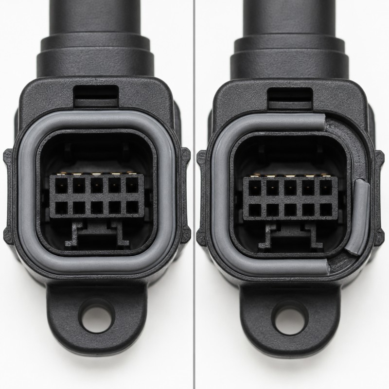
An LSR short shot is a molded part in which the silicone has not completely filled the intended product geometry.
The defect may appear as:
- A completely missing feature
- A shortened sealing lip
- A rounded edge where a sharp feature was expected
- A thin or transparent-looking section
- A rough final-flow area
- A partially filled hole
- An incomplete locking structure
- Exposed substrate
- An uneven boundary
- A part that weighs less than the approved sample
A short shot does not always mean that the entire product is visibly incomplete.
A precision connector seal may be missing only a small section of one lip.
An FPC overmolded component may have incomplete silicone coverage only around one corner of the stiffener.
A metal terminal may be fully covered on three sides but exposed at the final filling area.
Short-shot inspection should therefore focus on all critical features—not only the overall product outline.
2. Short Shots Must Be Distinguished From Other Defects
Several other defects can resemble incomplete filling.
Demolding Damage
A feature may have filled correctly but torn away during demolding.
Possible signs include:
- Torn edge
- Stress whitening
- Irregular fracture surface
- Material remaining inside the mold
- Damage concentrated around an undercut
Blocked or Protected Areas
Some holes, contact pads and connector openings are intentionally kept free of silicone.
An exposed area may be correct according to the drawing rather than a short shot.
Flow Marks or Weld Lines
The silicone may be present but show a visible flow boundary, cloudy line or gloss difference.
Thin Flash Being Removed
Aggressive trimming may accidentally remove part of a thin functional edge.
Insert Mispositioning
The silicone quantity may be correct, but the insert may have shifted and changed the apparent coverage.
Incorrect Drawing Interpretation
A customer may expect silicone in an area that was not included in the final mold design.
The investigation should first confirm whether silicone was never formed, formed and then damaged, or formed in the wrong location.
3. Short Shots Usually Appear at the Last-Filling Area
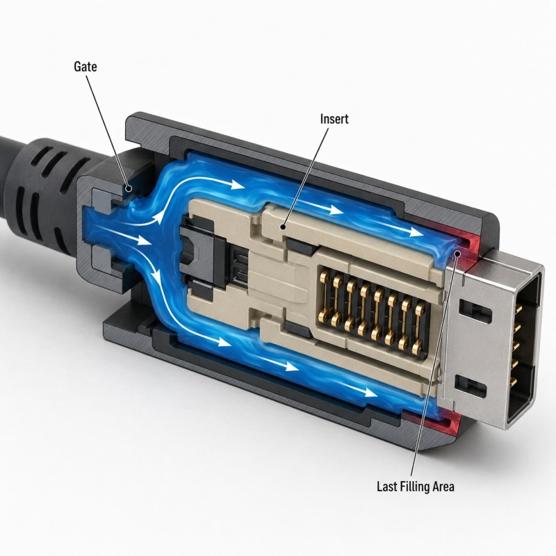
Liquid silicone flows outward from the gate and gradually fills the mold cavity.
The final filling area is the location reached last by the flow front.
Common last-filling areas include:
- The opposite side of the gate
- Behind a plastic or metal insert
- Around the end of an FPC stiffener
- At the end of a long sealing lip
- Inside a narrow groove
- At the tip of a small rib
- Around a cable exit
- Inside a deep mechanical lock
- Between two converging flow fronts
- At the end of a thin membrane
The final filling area normally has the greatest exposure to:
- Pressure loss
- Trapped air
- Early curing
- Flow imbalance
- Insert variation
- Venting problems
When a defect repeatedly appears in the same location, engineers should compare that position with the predicted final filling area.
4. Gate Position Determines the Main Flow Path
The gate is where liquid silicone enters the mold cavity.
Gate position affects:
- Flow direction
- Flow distance
- Cavity pressure
- Final filling location
- Air-trap location
- Insert loading
- Weld-line position
- Filling balance
- Flash risk
A gate positioned too far from a thin functional feature may require the silicone to travel through several wider and narrower sections before reaching it.
By the time the material reaches the final area:
- Pressure may be lower
- The flow front may have started curing
- Air may be trapped
- The insert may restrict the available space
A gate should not be positioned only according to convenient machining or product appearance.
It should be reviewed against:
- Critical sealing surfaces
- Thin-wall directions
- Insert geometry
- Vent locations
- Protected holes
- Cosmetic areas
- Mechanical locks
- Required flow balance
Gate position, final filling areas and critical dimensions should be reviewed during DFM before final tooling.
5. Inserts Divide and Restrict the Flow
An insert can block the direct path from the gate to the final cavity area.
The silicone may need to flow:
- Toward the insert
- Around the left and right sides
- Through narrow spaces
- Around holes, ribs or terminals
- Behind the insert
- Into the final thin section
The insert may be:
- Plastic
- Metal
- FPC
- Cable
- Connector
- Sensor housing
- Electronic module
- Pre-molded silicone
- Glass or ceramic
Small changes in insert geometry can significantly affect the flow path.
Examples include:
- A plastic rib narrowing one channel
- A metal terminal blocking a final filling area
- An FPC bowing toward one mold surface
- A cable shifting sideways
- A connector housing becoming warped
- A coating or plating increasing insert thickness
The actual production insert—not only the nominal CAD model—should be considered during mold-flow and filling evaluation.
6. Thin Sealing Lips Are High-Risk Filling Features
Thin sealing lips are used in:
- Waterproof connectors
- Sensor seals
- Charging-port seals
- Electronic housings
- Medical components
- Wearable devices
- Automotive interfaces
- Precision buttons
These structures are often positioned near the edge of the part and may be reached late in the filling process.
Incomplete filling may create:
- Missing lip sections
- Uneven lip height
- Rough edges
- Weak corners
- Local holes
- Reduced compression
- Leakage paths
A sealing lip may look almost complete but still fail because one small section does not produce continuous assembly contact.
The design should review:
- Lip thickness
- Lip height
- Flow direction
- Gate distance
- Vent position
- Parting-line location
- Compression surface
- Required flash control
Thin features require sufficient flow and venting margin rather than only high injection pressure.
7. Thin Membranes, Ribs and Narrow Bridges Can Freeze Early
Other high-risk structures include:
- Thin membranes
- Small ribs
- Narrow bridges
- Flexible hinges
- Fine protective skins
- Thin cable sleeves
- Micro-sealing rings
- Small valve structures
These areas provide less flow cross-section than thicker areas.
The silicone may hesitate or stop when it reaches a sudden restriction.
The risk increases when:
- The thin feature is far from the gate
- Several narrow features fill at the same time
- The material must turn sharply
- A rigid insert absorbs heat
- Air cannot escape
- The injection speed becomes unstable
A thin-wall design may be manufacturable, but its feasibility should be confirmed through DFM, mold trials and pilot production.
8. Abrupt Wall-Thickness Changes Redirect the Material
Silicone normally follows the path with lower flow resistance.
A thick section may fill before an adjacent thin section.
This can cause the material to:
- Bypass the thin feature
- Fill one side earlier
- Trap air at the thin feature
- Create unequal pressure
- Change the final filling location
High-risk transitions include:
- Thick overmold connected to a thin sealing lip
- Thick cable strain relief connected to a thin sleeve
- Thick button center connected to a membrane
- Thick plastic housing coverage beside a thin edge
- Large mechanical lock beside a narrow bridge
Gradual thickness transitions can produce more predictable flow.
Where the product requires a sudden transition, the gate and venting strategy should be designed specifically for that area.
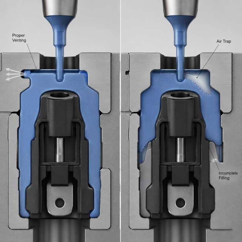
9. Poor Venting Can Stop the Flow Front
Air occupies the mold cavity before the silicone enters.
As the cavity fills, this air must escape.
If it cannot escape, the trapped air may resist the approaching silicone and create:
- Short shots
- Missing corners
- Rough final-flow areas
- Bubbles
- White edges
- Weak weld lines
- Burn-like discoloration
- Incomplete sealing lips
Dow recommends placing venting in the area reached last by the material and notes that good venting is necessary to avoid air entrapment during rapid LSR filling. SiliconePlus’s current venting guide also identifies incomplete thin sealing lips and small ribs as typical consequences of restricted air release.
A controlled mold venting design should be developed around the predicted final filling areas.
Venting should be reviewed according to:
- Gate location
- Final filling area
- Insert geometry
- Flow-front direction
- Wall thickness
- Required flash limit
- Mold shutoff
- Vacuum system
- Cleaning interval
Increasing vent depth without analysis may reduce short shots but create excessive flash.
10. Vacuum Assistance Cannot Correct Every Mold Problem
Some LSR molds use vacuum to remove air before or during filling.
Vacuum can help when the cavity contains:
- Deep enclosed areas
- Thin sealing lips
- Complex inserts
- Long flow paths
- Multiple final filling zones
However, a vacuum system cannot fully compensate for:
- Insufficient shot volume
- A blocked gate
- Early curing
- Severe cavity imbalance
- Insert movement
- Incorrect wall thickness
- Pre-cured material in the runner
- A damaged vent seal
Vacuum performance should also be verified through:
- Seal condition
- Vacuum level
- Vacuum timing
- Mold closing sequence
- Leakage inspection
- Maintenance records
A machine showing a vacuum signal does not automatically prove that every cavity has been evacuated correctly.
11. Insufficient Shot Volume Produces Underweight Parts
The dosing system must supply enough mixed LSR to fill:
- Runner volume
- Gate volume
- Product cavity
- Mechanical locks
- Thin sealing areas
- Expected process allowance
When the dosing volume is insufficient, the product may show:
- Consistently low weight
- Missing final-flow areas
- Shorter features
- Cavity imbalance
- Greater sensitivity to small parameter changes
Dow’s troubleshooting guidance lists insufficient dosage as a direct cause of underfilled LSR parts and recommends adjusting the dosing volume after confirming that the process and mold are stable.
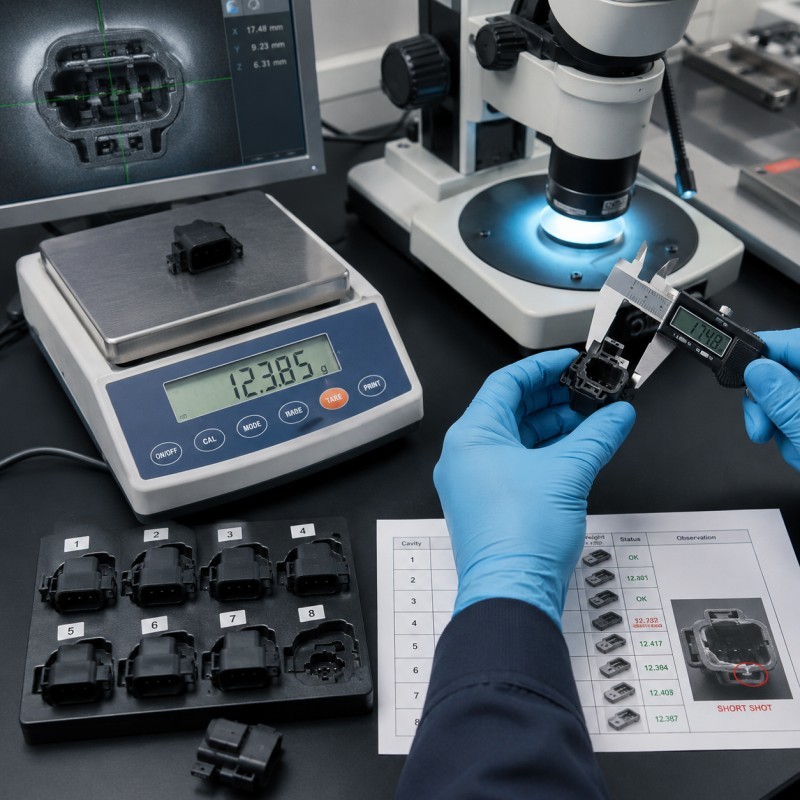
Part weight can be a useful process indicator.
Engineers can compare:
- Approved sample weight
- Individual cavity weight
- Beginning and end of the run
- Passing and failing parts
- Weight after a material or color change
However, a correct total weight does not prove that the material has filled the correct location.
Insert movement or excessive flash may increase weight while a critical sealing feature remains incomplete.
12. Injection Speed Affects Whether the Cavity Fills Before Curing
The injection-speed profile controls how quickly the silicone moves through the runner, gate and cavity.
If the speed is too low:
- Filling takes longer
- The material may begin curing before reaching the final area
- Thin features may stop filling
- Flow fronts may arrive at different times
- Surface marks may become more visible
If the speed is too high:
- Air may become compressed
- Insert movement may increase
- Flash may increase
- Sensitive FPC or terminals may shift
- Flow can become unstable near the end of filling
Dow recommends a sufficiently high initial volume flow so that the silicone does not begin vulcanizing before the cavity is filled, while reducing speed near the end to support air release. Its guide provides approximately 0.5–3 seconds as a general filling-time reference for the materials covered, not as a universal specification.
The correct profile may use:
- Faster initial filling
- Controlled transition
- Reduced final filling speed
- Stable switchover to holding pressure
The final settings must be established using the actual material, mold, insert and cavity-pressure response.
13. Higher Injection Pressure Is Not a Universal Solution
Increasing pressure may help push silicone into a restricted section.
However, excessive pressure can create:
- Flash
- Blocked contact pads
- Blocked holes
- Insert movement
- Plastic deformation
- FPC displacement
- Mold-shutoff leakage
- Uneven silicone thickness
- Higher cavity-to-cavity variation
This is especially important in overmolding, where the mold must simultaneously:
- Fill thin silicone areas
- Protect exposed openings
- Hold the insert
- Control flash
- Preserve bonding boundaries
SiliconePlus’s blocked-opening guide explains that operators may respond to incomplete filling by increasing pressure or shot volume, but this can force silicone into protected gaps and create blockage elsewhere.
Pressure should be adjusted only after reviewing:
- Shot size
- Gate restriction
- Injection speed
- Venting
- Insert position
- Wall thickness
- Mold temperature
- Material supply
- The process should also prevent LSR from blocking holes, contact pads and connector openings while improving the underfilled area.
14. Holding Pressure Has a Different Role in LSR Molding
Holding pressure in LSR molding should not be treated exactly like thermoplastic packing pressure.
Because LSR expands as it heats, holding pressure primarily helps prevent material from flowing backward through the gate before the gate area has cured sufficiently.
If the switchover or holding stage is incorrect, the process may show:
- Material backflow
- Incomplete final filling
- Part-weight variation
- Flash
- Unstable cavity pressure
Dow notes that the suitable holding time depends strongly on the gate design and that the gate must cure sufficiently to prevent material from escaping from the cavity.
The process should define:
- Injection-to-hold switchover
- Holding pressure
- Holding time
- Gate type
- Needle shutoff timing
- Cavity-pressure response
15. Mold Temperature Can Cause Early or Unstable Curing
LSR cures inside a heated mold.
If the temperature is too high relative to filling speed and flow distance, the material may begin curing before it reaches the final thin areas.
If the temperature is too low or uneven, the product may:
- Cure inconsistently
- Remain weak
- Stick during demolding
- Show unstable dimensions
- Require a longer cycle
The risk of early curing is affected by:
- Mold temperature
- Insert temperature
- Material temperature
- Flow distance
- Wall thickness
- Injection speed
- Production interruptions
- Material grade
Dow identifies mold temperature, insert temperature, material temperature and product geometry as important factors influencing LSR curing behavior.
The mold-temperature plan should also consider sensitive plastic, FPC, adhesive and electronic inserts.
16. Cold Inserts Can Change Local Flow and Cure
Plastic, metal and electronic inserts may enter the mold at a lower temperature than the mold cavity.
The insert can change:
- Local silicone viscosity
- Cure timing
- Flow-front speed
- Pressure distribution
- Final filling position
Metal inserts may transfer heat quickly.
Large plastic housings may create broad temperature differences.
FPC assemblies may contain stiffeners, copper, adhesive and electronic components with different thermal behavior.
The process should consider:
- Insert storage temperature
- Time between loading and injection
- Insert mass
- Insert material
- Mold contact area
- Preheating requirements, when applicable
- Maximum safe insert temperature
Production samples should use inserts under conditions representative of normal mass production.
17. Restricted Gates, Nozzles or Cold Runners Reduce Material Flow
The material path before the cavity may contain:
- Static mixer
- Injection unit
- Nozzle
- Cold runner
- Needle valve
- Gate
- Small runner branches
Restrictions can result from:
- Gate dimension too small
- Needle opening variation
- Runner imbalance
- Pre-cured silicone
- Damaged shutoff needle
- Inadequate cooling
- Material leakage
- Contamination
- Equipment wear
Possible symptoms include:
- Increasing injection time
- Lower part weight
- One cavity short-shooting
- Irregular cycles
- Starting problems after a production break
- Sudden appearance of missing features
Dow identifies pre-cured material in the injection unit or supply system as a possible cause of underfilled parts and recommends cleaning affected material paths.
18. Metering and Mixing Stability Affect Every Shot
LSR is normally supplied as two components that must be metered and mixed in the required ratio.
Process instability may result from:
- Uneven pump pressure
- Material-container changes
- Air entering the supply system
- Static-mixer blockage
- Non-return valve problems
- Color-paste dosing variation
- Material leakage
- Pre-cured areas
- Irregular dosing time
Symptoms may include:
- Variable shot weight
- Irregular injection time
- Partial curing
- Tacky areas
- Short shots
- Appearance variation
- Cycle instability
WACKER and Momentive describe LSR as a two-component system normally delivered through metering and static-mixing equipment before injection into the heated mold.
Production records should track:
- Dosing time
- Pump pressure
- Injection time
- Material batch
- Mixer replacement
- Color system
- Start-up and shutdown conditions
19. Insert Positioning Changes the Available Flow Space
A small insert shift can narrow one side of the silicone cavity.
The opposite side may then become wider.
This can cause:
- One side filling first
- One thin channel becoming blocked
- Uneven silicone thickness
- Short shots behind the insert
- New air traps
- Different weld-line locations
- Exposed substrate
Insert movement may include:
- Horizontal shift
- Vertical shift
- Rotation
- Tilting
- FPC bowing
- Cable movement
- Terminal displacement
- Plastic warpage
A mold-flow analysis based on a perfectly positioned insert may not represent actual production if the insert-loading and locating system is unstable.
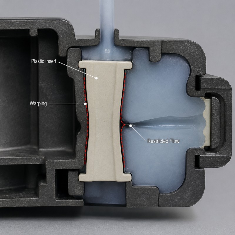
20. Plastic Insert Deformation Can Close a Flow Channel
A plastic insert may be correctly positioned when the mold closes but deform during heating or injection.
Silicone over plastic projects require the substrate to maintain stable flow gaps throughout injection and curing.
Possible deformation includes:
- Warping
- Bowing
- Shrinkage
- Local wall movement
- Rib deflection
- Hole distortion
The plastic may then narrow or completely close a silicone flow path.
Possible results include:
- Missing silicone on one side
- Uneven coverage
- Exposed plastic
- Short sealing lips
- Flash on the opposite side
- Assembly interference
SiliconePlus’s current plastic-insert guide notes that LSR flow and pressure can push or deform an insufficiently supported plastic insert, changing the final silicone structure.
Plastic geometry, heat resistance, residual stress, locating support and actual molding conditions should be reviewed together.
21. Metal, FPC and Cable Inserts Create Different Filling Risks
Metal Inserts
Metal components may contain:
- Small terminals
- Stamped holes
- Burrs
- Threads
- Narrow gaps
- Sharp corners
- Plated surfaces
These features can split or restrict the silicone flow.
FPC Inserts
FPC can:
FPC silicone overmolding requires stable circuit positioning, controlled pressure and sufficient flow space above and below the flexible insert.
- Bow
- Move
- Flex under pressure
- Create different gaps above and below the circuit
- Block a narrow silicone channel
- Shift exposed contact boundaries
SiliconePlus’s FPC guidance identifies controlled pressure, stable insert positioning and suitable venting as important for preventing air traps and incomplete filling.
Cable Inserts
Cable position can change because of:
- Bending
- Tension
- Diameter variation
- Jacket softness
- Fixture variation
- Operator loading
A shifted cable may narrow one side of a strain-relief cavity and create missing silicone or uneven wall thickness.
Each insert type requires its own locating, support and flow strategy.
22. Multi-Cavity Molds Require Balanced Filling
A multi-cavity mold may produce:
- Several identical parts
- Left and right components
- Different component sizes
- Multiple inserts in one shot
Every cavity should receive a controlled volume and pressure history.
Imbalance may result from:
- Different runner length
- Different gate dimensions
- Needle timing
- Temperature variation
- Venting differences
- Insert variation
- Tool wear
- Cold-runner blockage
One cavity may fill correctly while another repeatedly short-shoots.
Momentive’s processing guidance identifies balanced gates and venting as important for avoiding air entrapment and ensuring consistent cavity filling.
Multi-cavity validation should record:
- Cavity number
- Part weight
- Injection sequence
- Final filling location
- Defect frequency
- Cavity pressure, when available
- Beginning and end of the run
23. Pre-Cured Particles Can Block Small Flow Paths
Partially cured silicone can form inside:
- Supply hoses
- Static mixers
- Injection units
- Cold runners
- Nozzles
- Gates
- Dead zones
A particle may:
- Restrict the gate
- Block one runner branch
- Enter the cavity
- Interrupt a thin sealing lip
- Produce an embedded defect
- Reduce shot consistency
The problem may appear suddenly after:
- A production interruption
- A long shutdown
- Inadequate cooling
- Material leakage
- Extended residence time
- Maintenance problems
Cleaning only the mold cavity may not solve a defect originating upstream in the metering or runner system.
24. Why Can Samples Fill Correctly but Mass Production Develop Short Shots?
Engineering samples are normally produced under close supervision.
During sampling:
- Inserts are selected carefully
- Mold surfaces and vents are clean
- Production runs are short
- Injection parameters are adjusted slowly
- Engineers inspect every part
- Equipment has limited material residence time
- Only one material batch may be used
Mass production introduces:
- Longer continuous runs
- Vent contamination
- Cold-runner deposits
- Gate wear
- Multiple insert batches
- Operator changes
- Mold-temperature drift
- Dosing variation
- Tool wear
- Faster loading
- Production interruptions
A process with limited filling margin may produce acceptable samples but become unstable after hundreds or thousands of cycles.
SiliconePlus’s prototype-to-production guide emphasizes that stable material, tooling, insert positioning, process parameters and inspection are required to maintain repeatable overmolded quality during longer production runs.
25. A Practical Short-Shot Failure-Analysis Sequence
When an LSR overmolded part shows missing silicone or incomplete filling, investigate systematically.
Recommended sequence:
- Confirm the drawing revision.
- Mark the exact missing area.
- Determine whether the feature was never filled or was torn after molding.
- Identify the mold-cavity number.
- Compare passing and failing samples.
- Weigh each cavity separately.
- Confirm the insert position.
- Measure the actual flow gap around the insert.
- Identify the gate and expected final filling area.
- Inspect vents for blockage or damage.
- Review vacuum performance, when used.
- Review shot volume and dosing consistency.
- Review injection-speed profile.
- Review injection pressure and switchover.
- Review holding pressure and gate behavior.
- Check mold-temperature uniformity.
- Check insert temperature and deformation.
- Inspect gates, needles, cold runners and nozzles.
- Check for pre-cured particles.
- Review material and color-batch changes.
- Compare beginning and end of the production run.
- Change one controlled variable.
- Repeat production and document the result.
Do not simultaneously increase pressure, enlarge the shot size, deepen vents and change mold temperature.
Changing one controlled variable at a time makes the root cause easier to confirm.
26. What Should Be Validated Before Mass Production?
Before approving a precision LSR overmolded part, buyers and manufacturers should confirm:
- Final LSR grade
- Silicone hardness
- Substrate material
- Insert dimensions
- Insert tolerance
- Insert-positioning method
- Plastic-deformation risk
- Gate position
- Gate dimensions
- Runner balance
- Needle timing
- Expected flow direction
- Final filling areas
- Thin-wall dimensions
- Sealing-lip dimensions
- Rib and membrane dimensions
- Mechanical-lock dimensions
- Vent position
- Vent dimensions
- Vacuum requirement
- Shot volume
- Injection-speed profile
- Injection-pressure window
- Switchover point
- Holding-pressure conditions
- Mold-temperature range
- Insert-temperature condition
- Dosing and mixing control
- Part-weight range
- Cavity identification
- Appearance standard
- Functional sealing test
- Pilot-production quantity
- Continuous-run evaluation
- Mold-cleaning interval
- Vent-cleaning interval
- Reference sample
- Traceability records
Approval should not be based only on the overall product outline.
Every functional lip, rib, membrane, lock, edge and protected interface should be inspected.
Filling improvement should be coordinated with flash and tolerance control so that thin functional areas can fill without creating silicone leakage at mold shutoffs or insert boundaries.
How SiliconePlus Supports LSR Filling and Flow-Control Projects
SiliconePlus provides custom liquid silicone injection molding and silicone overmolding services for precision components used in:
- Automotive electronics
- 3C electronics
- Wearable devices
- Medical equipment
- Sensors
- Beauty devices
- Waterproof connectors
- Industrial equipment
Our project support can include:
- DFM and drawing review
- Thin-wall feasibility evaluation
- Gate and runner review
- Final filling-area analysis
- Mold-flow review
- Venting and vacuum evaluation
- LSR material and hardness selection
- Silicone over plastic
- Silicone over metal
- FPC silicone overmolding
- Cable and connector overmolding
- Insert-positioning development
- Custom mold development
- Process-window optimization
- Part-weight and cavity comparison
- Sample and pilot production
- Appearance and dimensional inspection
- Waterproof-test coordination
- OEM/ODM mass production
With 25+ years of silicone manufacturing experience, our team reviews the complete relationship between:
- Product geometry
- Insert structure
- Material flow
- Gate
- Runner
- Venting
- Temperature
- Injection parameters
- Continuous-production stability
The objective is not only to fill one engineering sample.
The objective is to maintain complete silicone coverage and functional feature integrity across mold cavities, insert batches, material batches and continuous production runs.
What Information Should Buyers Send for Evaluation?
To evaluate an LSR short-shot or incomplete-filling project, buyers should provide:
- 2D drawing
- 3D file
- Product photographs
- Defect close-up photographs
- Physical samples, when available
- Substrate material
- Insert drawing
- Insert tolerance
- Silicone material
- Silicone hardness
- Silicone coverage area
- Thin-wall dimensions
- Sealing-lip dimensions
- Critical functional areas
- Gate information, when available
- Mold-cavity number
- Part-weight data
- Known process parameters
- Waterproof requirement
- Electrical-insulation requirement
- Current production quantity
- Affected quantity
- Estimated future quantity
When possible, provide passing and failing parts from different cavities, production times and insert batches.
Frequently Asked Questions
Why does LSR produce a short shot even though it flows easily?
High flowability helps LSR enter thin features, but filling can still stop because of trapped air, insufficient shot volume, restricted gates, early curing, long flow paths, insert movement or process instability.
Where do short shots usually appear?
They commonly appear at the final filling area, behind inserts, at the ends of sealing lips, inside narrow ribs, around mechanical locks and in thin membranes.
Can higher pressure eliminate incomplete filling?
Sometimes pressure adjustment helps, but excessive pressure may create flash, blocked openings, insert movement or plastic deformation. The complete flow and venting system should be reviewed first.
Can increasing the shot volume solve the problem?
It may help when the dosage is genuinely insufficient. However, excessive volume may create flash or blockage and will not correct a blocked vent, early curing or insert-position problem.
Why does only one mold cavity short-shoot?
Possible causes include runner imbalance, gate variation, vent blockage, needle timing, cavity temperature, insert positioning or cavity-specific tool wear.
Why does the defect appear only after long production runs?
Vents may become dirty, pre-cured material may accumulate, gates or cold runners may become restricted, insert batches may change or process temperatures may drift.
Can a short shot cause waterproof failure?
Yes. A missing or incomplete sealing lip can reduce compression continuity and create a leakage path even when the rest of the part looks acceptable.
How can short shots be inspected?
Inspection may include visual checking, optical measurement, part weighing, cavity traceability, pin gauges, section analysis, assembly testing, leak testing and comparison with approved reference samples.
Can mold-flow simulation predict incomplete filling?
Simulation can help identify flow paths, pressure loss, weld lines and likely air traps, but actual inserts, material behavior, venting, temperature and equipment conditions must still be validated through mold trials.
What should buyers approve before bulk production?
Buyers should approve the material, insert, gate, flow path, vents, thin features, part-weight range, appearance standard, functional tests, cavity consistency and pilot-production results.
Conclusion
LSR short shots, missing edges and incomplete filling are not caused by one universal machine parameter.
The defect may result from insufficient shot volume, unsuitable injection speed, restricted gates, long flow paths, trapped air, poor venting, early curing, unstable mold temperature, insert movement, plastic deformation, cavity imbalance or pre-cured material.
Because LSR can also flow into extremely small gaps, solving a short shot by increasing pressure or volume may create flash, blocked holes or insert displacement elsewhere.
The most reliable approach is to identify the actual final filling area, review the complete product and insert geometry, establish a balanced gate and venting strategy, stabilize the material and process system, and validate every cavity during pilot production.
If you are developing an LSR overmolded connector, FPC component, cable assembly, sensor, plastic housing, metal insert or waterproof seal with missing silicone or incomplete thin features, contact SiliconePlus and send us your drawings, substrate information, defect photographs, cavity number, silicone requirement, functional areas, test standards and estimated quantity. Our engineering team will review the project and provide practical manufacturing recommendations.