How Should an LSR-Overmolded Fuel Cell Bipolar Plate Seal Be Designed Before Tooling?
Answer Excerpt
An LSR-overmolded fuel cell bipolar plate seal should be designed around clearly defined perimeter and manifold sealing paths while keeping flow-field channels, port openings and specified electrical contact areas unobstructed. Before tooling, engineering teams should confirm the metal substrate and surface condition, seal geometry, insert positioning, stack alignment and compression requirements, mold shut-off strategy, and application-specific validation plan. Final acceptance must be based on the customer's fuel cell stack design and qualification requirements.
Why Does a Fuel Cell Bipolar Plate Seal Need a Dedicated Design Review?
A fuel cell bipolar plate is not simply a flat metal part with a rubber gasket added afterward. Its sealing areas must work with the plate geometry, manifold openings, adjacent stack components and the intended compression condition.
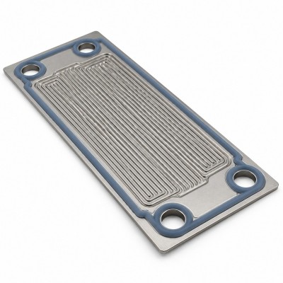
For a custom LSR-overmolded fuel cell bipolar plate seal, liquid silicone rubber is molded onto defined areas of a customer-supplied metallic bipolar plate. The intended seal may follow the external perimeter and designated manifold regions, while flow-field channels, port openings and specified electrical contact zones remain exposed.
These functional areas must be defined on the approved drawing before mold design begins. The exact layout varies with the customer's plate architecture, so a generic seal profile should not be assumed to fit every project.
SiliconePlus lists this integrated metal-and-silicone component as a custom manufacturing product. The scope is the agreed overmolded component; complete fuel cell stack assembly and system qualification remain subject to the customer's requirements and any separately agreed scope.

How Should the Sealing Paths and Keep-Out Zones Be Mapped?
Start with a drawing that separates the sealing areas from the regions that must remain open. Do not rely on a rendered product image alone to communicate these boundaries.
The design review should identify the following zones:
- Perimeter sealing path: Define the intended sealing route around the plate boundary, including corners, transitions and any changes in direction.
- Manifold sealing regions: Identify the openings that require sealing around their perimeter. Confirm that the seal does not reduce the required opening area.
- Flow-field channels: Mark the channels and related flow areas that must remain exposed. Silicone flash or unintended coverage in these regions should be treated as a functional concern.
- Electrical contact zones: Explicitly identify any specified metal surfaces that must remain exposed for electrical contact or other defined functions.
- Mating and alignment references: Show the datums or features used to locate the plate and compare the seal path with its mating component.
Each zone should have a clear drawing reference and an agreed inspection method. If a boundary is critical to stack assembly or function, define its allowable position and appearance rather than leaving the decision to visual judgment during production.
Functional Zone Design Review
| Functional zone | What the drawing should define | What to review before tooling |
Perimeter sealing path | Continuous intended seal route and reference datums | Path continuity, corner transitions and boundary position |
Manifold openings | Opening locations and designated sealing regions | Opening clearance, seal alignment and flash-sensitive edges |
| Flow-field channels | Areas that must remain exposed | Risk of unintended silicone coverage or obstruction |
| Electrical contact zones | Specified no-silicone areas | Contact-surface clearance and inspection visibility |
| Mating interface | Related stack components and alignment references | Position tolerance, compression requirements and assembly fit |
What Metal Substrate Information Should Be Confirmed?
The metal substrate and its surface condition are part of the overmolding design, not details to be confirmed only after samples are produced.
Before tooling, the buyer should provide the available substrate specification and identify any surface treatment or coating. The review should cover the metal grade, thickness, forming condition, surface finish or coating, dimensional references, flatness requirements and any known handling or contamination restrictions relevant to the project.
Silicone-to-metal adhesion must not be assumed solely because the two materials can be placed in the same mold. The selected LSR, metal surface, surface preparation and molding conditions need to be evaluated for the intended application. Depending on the design, the engineering review may also consider whether adhesion, mechanical retention or a combination is required.
SiliconePlus provides silicone over metal overmolding capabilities for custom components. Feasibility should be reviewed against the actual substrate drawing and surface specification, rather than relying on a general statement that silicone can be molded over metal.
How Should Seal-Bead Geometry and Stack Compression Be Reviewed?
The seal cross-section must be evaluated together with the mating stack structure. A bead that looks continuous on the isolated metal plate is not, by itself, proof that the assembled interface will seal correctly.
Review the following items before approving the mold design:
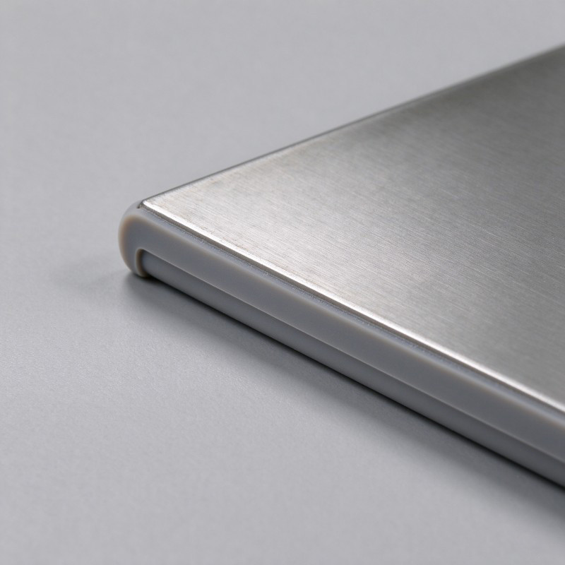
- Seal cross-section: Define the intended shape and dimensions of the sealing bead on the drawing.
- Position relative to datums: Establish how the bead is located relative to the plate edges, manifold openings and other functional features.
- Corner and transition geometry: Check whether changes in direction or intersections create difficult-to-control areas.
- Mating surface condition: Identify the component or surface against which the seal will be compressed, including relevant flatness and alignment requirements.
- Stack compression: Provide the intended assembly condition and the allowable compression range, where defined by the customer's design.
- Material and durability requirements: Specify the operating media, temperature conditions and required service or cycle expectations so the selected material and validation plan can be assessed.
There is no universal bead height, silicone hardness or compression value that can be safely applied to every bipolar plate design. These values must be derived from the actual stack geometry, material selection, assembly load and functional requirements, then verified through an agreed evaluation plan.
Seal Geometry and Compression Review
| Review item | Information needed | Why it matters |
Bead cross-section | Drawing dimensions and geometry | Defines the intended sealing profile |
Bead location | Datums and position requirements | Connects seal placement to the plate and mating parts |
Corner transitions | Detailed geometry at turns and intersections | Helps identify local filling, flash and inspection risks |
| Mating surface | Surface condition and dimensional requirements | Supports evaluation of the assembled sealing interface |
| Stack compression | Customer-defined assembly condition and limits | Avoids selecting seal geometry independently of the stack |
| Material requirements | Media, temperature and durability conditions | Supports application-specific material review and validation |
What Should the Mold Design Control?
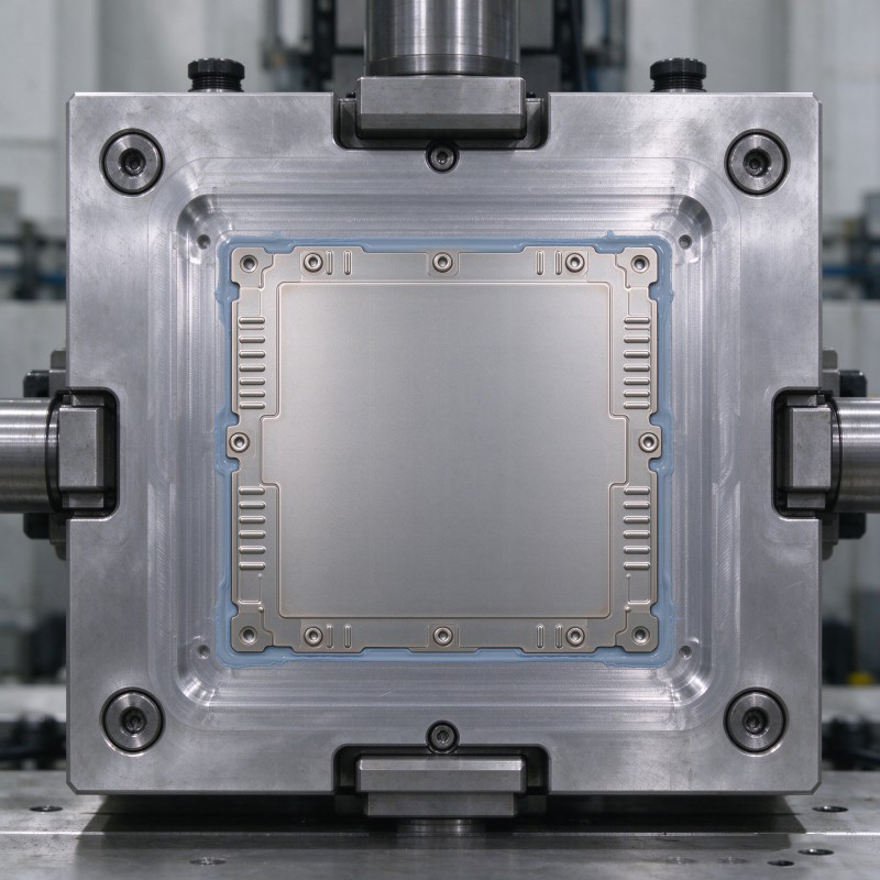
A metal bipolar plate must be located consistently in the mold so that the silicone sealing path remains aligned with the approved drawing. The tooling review should consider how the plate is supported, how its position is established and how movement during molding will be prevented.
Parting lines and shut-off surfaces deserve particular attention around manifold openings, flow-field boundaries and specified exposed metal zones. Flash in a non-functional area may be cosmetic, while flash that enters an opening or covers a required contact area may affect the component's intended function.
The mold review should also consider gate and venting locations, filling around the full sealing path, insert loading and unloading, demolding, and access for inspection. These choices must be based on the actual part geometry and molding feasibility review.
Before approving tooling, use silicone mold design capabilities as a point of reference for the type of design and tooling support available, then confirm the proposed solution against the specific plate drawing. No single mold layout should be assumed suitable for all fuel cell bipolar plates.
How Should Samples Be Validated Before Production Approval?
Sample approval should evaluate the molded component and its intended assembled interface. A visually complete silicone bead does not establish that the finished stack will meet its leakage or durability requirements.
A project-specific validation plan may include:
- Dimensional inspection: Check seal-path position, relevant bead dimensions and the locations of functional openings and exposed zones against the approved drawing.
- Visual inspection: Look for incomplete filling, flash, surface defects or unintended silicone coverage in critical areas.
- Interface review: Examine the silicone-to-metal interface and verify that the agreed adhesion or retention requirements are addressed.
- Representative assembly evaluation: Assess the component in the relevant mating or stack arrangement, using the customer's defined alignment and compression conditions.
- Leakage testing: Agree on the test medium, pressure, temperature, duration, fixture, acceptance criteria and reporting method before testing.
- Durability evaluation: Where required, define the relevant thermal, media-exposure, compression or cycling conditions and acceptance criteria.
The test method and acceptance limits must come from the customer's application specification. SiliconePlus can review the component-level requirements and support sample evaluation; complete fuel cell stack performance and system qualification should not be inferred from a component sample alone.
The process should use liquid silicone injection molding requirements that match the selected LSR, metal substrate and approved tooling design. Material selection and molding feasibility should be confirmed before final production approval.
Pre-Production Validation Plan
| Validation area | What to define before testing | Evidence to retain |
Dimensions | Drawing revision, critical dimensions and inspection method | Inspection record against the approved drawing |
Visual quality | Acceptable appearance and critical flash-sensitive areas | Visual inspection record and defect criteria |
Metal-silicone interface | Required adhesion or retention approach | Agreed evaluation results |
| Assembly | Mating parts, alignment references and compression condition | Representative assembly evaluation |
| Leakage | Test medium, pressure, temperature, duration and acceptance limits | Test procedure and recorded results |
| Durability | Required exposure or cycling conditions, if applicable | Results against the customer-defined criteria |
What Should Buyers Include in an RFQ?
A clear RFQ helps the manufacturer assess overmolding feasibility, identify missing design information and prepare a more meaningful quotation. For a custom fuel cell bipolar plate seal, buyers should provide as much of the following information as is available:
1. 2D drawing and 3D CAD: Include the plate geometry, proposed seal path, relevant datums and functional openings.
2. Metal substrate details: Identify the material grade, thickness, forming condition and any coating or surface treatment.
3. Seal definition: Mark the perimeter and manifold sealing areas, flow-field keep-out zones and specified exposed contact regions.
4. Mating stack information: Describe the related components, alignment requirements and intended compression condition.
5. Operating environment: State the intended gas or coolant media, temperature range and other relevant conditions.
6. Acceptance requirements: Define leakage limits, test methods, durability expectations and inspection criteria where established.
7. Quantity and schedule: Provide prototype needs, estimated production volume, forecast and target timing.
If some details are not yet available, identify them as open engineering items rather than guessing. The purpose of the initial DFM review is to clarify feasibility, risks and missing requirements before the project commits to tooling.
Frequently Asked Questions
Can LSR Be Overmolded Directly Onto a Metal Fuel Cell Bipolar Plate?
LSR overmolding onto a metallic bipolar plate can be evaluated as a custom metal-insert molding process. Feasibility depends on the plate geometry, substrate surface condition, selected LSR, tooling design and the project's adhesion or retention requirements. The material combination must be validated for the intended application.
Can the Seal Be Integrated Around the Plate Perimeter and Manifold Openings?
The seal design can define molded sealing paths around selected perimeter and manifold regions. The drawing must also identify the flow-field channels, port openings and specified electrical contact areas that must remain exposed. The exact arrangement depends on the customer's bipolar plate design.
Does Silicone Automatically Bond to Every Metal Surface?
No. Bonding performance depends on the selected silicone, metal type, coating or surface treatment, surface condition and molding process. The project should establish whether adhesion, mechanical retention or a validated combination is required.
Is There a Standard Compression Value for Every Bipolar Plate Seal?
No universal value should be assumed. The required compression depends on the seal geometry, selected material, mating surfaces, stack structure and assembly conditions. The customer's design requirements and representative validation should determine the acceptable range.
Does Approval of the Overmolded Component Qualify the Complete Fuel Cell Stack?
Not automatically. Component inspection and validation address the agreed part-level requirements. Complete stack assembly, operating performance and system qualification remain subject to the customer's broader validation programme unless those activities are separately included in the project scope.
Conclusion
An LSR-overmolded fuel cell bipolar plate seal should be developed as part of the customer's stack interface, not as an isolated silicone shape. The most important pre-tooling tasks are to map the sealing paths and keep-out zones, document the metal substrate, coordinate seal geometry with stack compression, control insert positioning and mold shut-off, and agree on a representative validation plan.
These checks help the engineering and sourcing teams identify missing requirements before tooling decisions are finalized. Final seal dimensions, material selection, leakage criteria and durability requirements must be established for the specific application and verified against the customer's specifications.
Discuss Your Fuel Cell Bipolar Plate Seal Project
Developing a metallic bipolar plate that requires an integrated LSR sealing structure?
SiliconePlus supports custom silicone-over-metal projects through DFM review, tooling development, sampling and agreed component-level inspection. Share your 2D drawing, 3D CAD, substrate details, proposed sealing areas and application requirements so the project can be reviewed before tooling.
To discuss your design and manufacturing requirements, contact SiliconePlus for an engineering review and quotation.