When Does LSR Overmolding Need Mechanical Retention?
Answer Excerpt
Mechanical retention should be added to LSR overmolding when the silicone-to-insert interface may experience peeling, pulling, bending, vibration, thermal cycling or uncertain material compatibility. Chemical adhesion can improve sealing and interface strength, but holes, grooves, undercuts and edge wraparound provide an additional physical lock that protects the assembly if adhesion becomes weaker over time.
LSR overmolding may rely on self-bonding silicone, primer, plasma treatment, mechanical retention or a combination of these methods.
A material pair may show acceptable adhesion during the first sample trial but still fail after repeated bending, humidity exposure, temperature changes or long-term loading.
This happens because the interface is not exposed only to a simple pulling force.
The silicone may be peeled from an edge, twisted around an insert, compressed during assembly or repeatedly expanded and contracted at a different rate from the plastic, metal, FPC or cable substrate.
Mechanical retention reduces the risk of complete separation by allowing the cured silicone to lock physically into the insert structure.
For multi-material components, plastic with silicone overmolding should be reviewed together with bonding, mechanical loading and final environmental requirements.
Why Is Chemical Adhesion Alone Sometimes Insufficient?
Chemical adhesion depends on the exact silicone grade, substrate formulation, surface condition and molding process.
Bonding consistency may be affected by:
• Plastic additives
• Glass-fiber content
• Flame retardants
• Mold-release residue
• Surface oils or dust
• Moisture
• Primer application
• Plasma-treatment conditions
• Mold temperature
• Cure time
• Material-lot variation
• Substrate-supplier changes
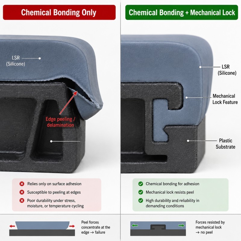
A flat bonded surface may perform well under compression or shear but remain vulnerable to peeling from an exposed edge.
Peel loading is especially damaging because the force is concentrated along a narrow interface instead of being distributed across the complete bonding area.
Mechanical retention does not eliminate the need for material compatibility and process control.
It adds a second protection mechanism so that the complete joint does not depend only on chemical adhesion.
When Should Mechanical Retention Be Added?
Mechanical retention is recommended when one or more of the following conditions apply:
• The substrate has uncertain chemical compatibility
• The silicone edge is exposed to peeling
• The product experiences cable pulling or repeated bending
• The assembly is exposed to vibration
• Thermal cycling may stress the interface
• The silicone forms a strain relief or flexible hinge
• Waterproof failure would damage electronics
• The plastic or cable supplier may change
• The part is exposed to oils, cleaners or humidity
• Long-term field reliability is more important than minimum tooling complexity
Mechanical retention is especially useful around connector housings, cable exits, sensor frames, electronic enclosures and sealing structures.
It may not be necessary on every surface.
The lock should be added where the main load enters the silicone or where interface separation would create a leakage path.
Which Mechanical Locking Structures Are Commonly Used?
Different mechanical-locking structures provide different load paths and molding risks.
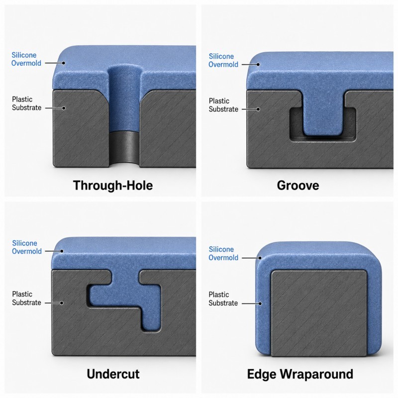
Through-Holes
LSR flows through the insert and connects the silicone on both sides.
This creates a strong physical anchor, but the hole must fill completely and allow trapped air to escape.
Grooves
Circumferential or linear grooves increase the locking path between the silicone and insert.
The groove should not be so deep or narrow that it creates an air trap or short shot.
Undercuts
An undercut allows the cured silicone to lock behind the insert geometry.
The mold and product must still permit safe demolding without tearing the silicone.
Edge Wraparound
Silicone wraps around an insert edge instead of ending on one flat surface.
This can reduce direct peeling at the interface termination.
Slots and Windows
Slots allow silicone to create multiple local anchors in plastic or metal frames.
They are useful when the product cannot use one large through-hole.
Textured Retention Surface
Controlled ribs or surface texture may improve physical grip, but texture alone should not be treated as equivalent to a true through-lock structure.
What Are the Most Common Mechanical-Retention Design Mistakes?
A mechanical lock can improve reliability, but an unsuitable structure may introduce new molding defects.
Common mistakes include:
• Retention holes that are too small to fill reliably
• Deep grooves without venting
• Sharp corners that tear the silicone
• Locks located too far from the loaded edge
• Excessively thin silicone around an anchor
• Insert walls that deform under injection pressure
• Retention structures positioned directly in a critical sealing surface
• Undercuts that make demolding difficult
• Too many isolated locks creating trapped air
• Insert movement changing the lock position
The retention feature should be located close to the actual load path.
For example, a cable strain relief should transfer pulling and bending force into the connector housing instead of relying on a small lock far from the cable exit.
Insert positioning must also remain stable so that the silicone thickness and retention-feature filling remain consistent.
Review how insert positioning affects custom LSR overmolding quality when the insert contains small holes, grooves or functional openings.
Mechanical Retention DFM Checklist
| DFM Item | What Engineers Should Confirm | Main Risk |
Load direction | Pull, peel, bend, twist or compression is defined | Lock positioned away from the real load |
Substrate material | Exact plastic, metal, FPC or cable grade is confirmed | Unstable adhesion or deformation |
Lock type | Hole, groove, slot, undercut or wraparound is selected | Structure does not match the application |
Silicone thickness | Enough material surrounds the lock | Tearing or incomplete filling |
Flow path | LSR can reach every retention feature | Short shot or weld line |
Venting | Trapped air can escape | Hidden voids or bubbles |
| Insert support | Insert cannot move or bend | Uneven lock geometry |
| Edge radius | Sharp corners are removed | Silicone tearing |
| Demolding | Part can be removed without damaging the lock | Permanent deformation |
Validation | Pull, peel, thermal and leak tests are defined | Sample passes but field use fails |
The silicone mold design and tooling review should evaluate the mechanical lock together with gate location, venting, shut-off, insert support, silicone flow and demolding direction.
How Should Mechanical Retention Be Validated?
Mechanical retention should be validated on molded parts under the actual application load direction.
Recommended validation includes:
1. Pull Test
Apply tensile force in the direction expected during product use.
Record the maximum force and failure location.
2. Peel Test
Where the geometry permits, peel the silicone from the insert edge to evaluate whether the lock prevents progressive separation.
3. Cross-Section Inspection
Cut selected samples through the retention structure to confirm complete filling, silicone thickness and absence of trapped air.
4. Repeated Bend or Torsion Test
Evaluate cable exits, flexible joints and wearable components under repeated movement.
5. Thermal Cycling
Confirm that expansion differences between silicone and the insert do not open the interface.
6. Leak Testing
For waterproof components, repeat the leak test after mechanical and environmental loading.
7. Pilot Production
Inspect multiple cavities and consecutive production cycles to confirm that every lock fills consistently.
The preferred failure mode should be defined according to the product. A strong lock may cause the silicone itself or the insert to fail before complete interface separation.
How SiliconePlus Supports Mechanical-Retention Design
SiliconePlus supports LSR overmolding projects from material and structural review through tooling, sampling, inspection and mass production.
Project support can include:
• Silicone-to-substrate compatibility review
• Mechanical-load and peeling-risk analysis
• Through-hole, groove and edge-lock design
• Insert-positioning and support review
• Gate and venting analysis
• Mold shut-off design
• Precision mold manufacturing
• LSR injection molding
• Cross-section and dimensional inspection
• Pull, bend and waterproof test support
• Pilot-production validation
SiliconePlus has 25 years of silicone manufacturing experience, more than 6,000 developed silicone projects, in-house CNC and EDM mold-processing capability, liquid silicone injection equipment and precision inspection resources.
Specific lock dimensions, pull force, bonding performance and waterproof requirements should be confirmed according to the actual product structure and agreed test method.
FAQ
Does Self-Bonding LSR Eliminate the Need for Mechanical Locks?
Not always. Self-bonding LSR can improve chemical adhesion, but mechanical retention may still be required for peeling, pulling, vibration or high-risk waterproof applications.
Are More Retention Holes Always Better?
No. Too many small holes can trap air, increase flow resistance and weaken the insert. The number and location should match the actual load path.
Can Mechanical Locks Replace Surface Cleaning?
No. The insert must still be clean and controlled. Contamination may create voids, weak interface areas or poor appearance even when a mechanical lock is present.
Where Should the Mechanical Lock Be Located?
It should be close to the load-entry point or interface edge that is most likely to peel, pull or open during use.
Can a Mechanical Lock Cause Silicone Tearing?
Yes. Sharp corners, insufficient silicone thickness or difficult demolding can create tearing around the retention feature.
How Do You Know Whether a Lock Is Fully Filled?
Use visual inspection, cross-section analysis, dimensional inspection and application-specific pull or peel testing.
Conclusion
Mechanical retention should be added when an LSR overmolded component cannot safely depend only on chemical adhesion.
Reliable design requires coordinated control of:
• Load direction
• Material compatibility
• Lock geometry
• Silicone thickness
• Gate and venting
• Insert support
• Edge radius
• Demolding
• Mechanical testing
• Environmental validation
The best time to add mechanical retention is during DFM, before the mold structure is finalized.
For a project-specific review, send your product drawing, substrate material, load direction and bonding requirements to the SiliconePlus engineering team.