Why Do Bubbles and Voids Form Around Inserts During LSR Overmolding?
Answer Excerpt
Bubbles and voids around inserts during LSR overmolding normally form when air, moisture or gas cannot escape before the silicone cures. Common causes include wet or contaminated inserts, closed-end grooves, poor mold venting, unsuitable gate direction and rapid filling around unsupported geometry. The insert, mold and molding process should therefore be reviewed as one complete system.
Liquid silicone rubber can flow into thin sealing lips, narrow channels and complex retention features.
This flowability makes LSR suitable for waterproof sealing and precision multi-material components, but it can also trap air around plastic, metal, FPC or cable inserts.
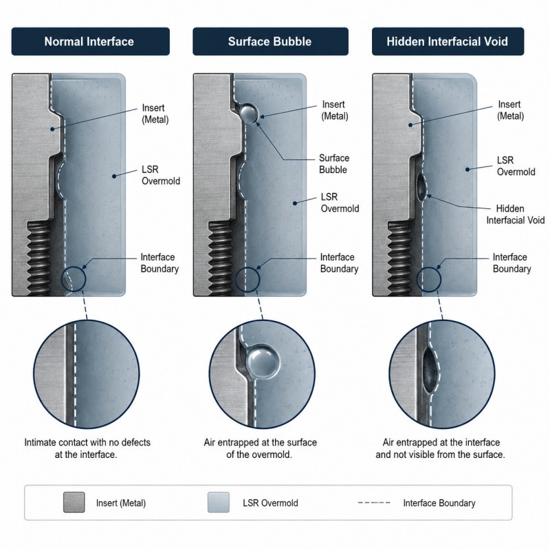
Some defects are visible on the surface. Others remain hidden at the silicone-to-insert interface and are only discovered during cross-section inspection, pull testing or waterproof validation.
For complex insert-molding projects, liquid silicone injection molding should be reviewed together with insert preparation, mold flow, gate location and venting.
Why Do Bubbles and Voids Form Around Inserts?
A bubble is a gas-filled defect that may appear on or beneath the silicone surface. A void is an unfilled or partially filled region inside the molded structure.
The main causes include:
• Moisture inside the insert
• Oil, dust or release-agent contamination
• Gas released from the plastic or adhesive
• Air trapped inside grooves or through-holes
• Insufficient mold venting
• Gate flow surrounding and sealing air too early
• Excessively fast filling
• Insert movement during injection
• Incomplete filling around mechanical locks
• An unstable mold-temperature or curing window
The location and shape of the defect normally provide clues about the actual cause.
1. Moisture or Contamination Is Present on the Insert
Plastic, FPC and cable inserts may absorb moisture during storage or handling.
When the insert enters a heated LSR mold, moisture or volatile substances may form gas at the silicone interface.
Possible contamination sources include:
• Moisture absorbed by PA or other hygroscopic plastics
• Processing oils
• Mold-release residue
• Operator fingerprints
• Dust
• Cleaning-agent residue
• Ink or printed markings
• Adhesive layers
• Recycled resin or uncontrolled additives
The incoming insert specification should define drying, storage time, handling and surface-cleanliness requirements.
Changing the plastic supplier, cable jacket or adhesive system may also change outgassing behavior and should trigger a new molding validation.
2. Air Cannot Escape from the Final Fill Area
As LSR fills the cavity, the air already inside the mold must escape.
Air is easily trapped in:
• Closed-end grooves
• Deep retention holes
• Thin sealing channels
• Areas behind the insert
• Terminal boundaries
• Cable interfaces
• Sudden thickness changes
• Final-fill corners
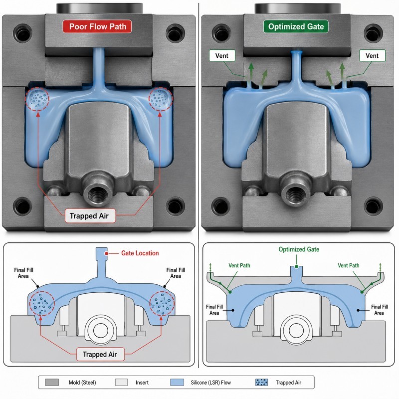
The vent should be placed where the flow fronts finish filling the cavity.
If the vent is missing, blocked or too small, trapped air may create a bubble, short shot or weak bonding area.
A vent that is too large may create excessive silicone flash, so venting must be balanced with the selected LSR grade and process conditions.
3. Gate Direction and Insert Geometry Trap Air
Gate direction determines how silicone flows around the insert.
If two flow fronts meet behind the insert, they may seal an air pocket before it reaches a vent.
High-risk geometry includes:
• Deep undercuts
• Blind holes
• Narrow channels
• Thick-to-thin transitions
• Unsupported insert edges
• Multiple mechanical locks
• Large inserts blocking the main flow path
The gate should fill the critical interface progressively rather than surrounding the insert from several directions at the same time.
Mechanical retention features must also be large enough to fill completely and positioned so that air can escape.
For plastic inserts, plastic with silicone overmolding should be evaluated using the actual resin, insert geometry and planned production conditions.
DFM Checklist for Preventing Bubbles and Voids
| DFM Item | What Engineers Should Confirm |
Insert material | Exact resin, cable jacket, adhesive or metal specification is confirmed |
Moisture control | Drying and storage requirements are defined |
Surface condition | Oil, dust and release agents are controlled |
Insert positioning | The insert remains stable during injection |
Gate location | Flow does not trap air behind the insert |
Final fill area | Air can reach a designed vent |
Venting | Vent size and location are suitable for the LSR grade |
Retention features | Holes and grooves can fill without trapping air |
| Wall thickness | Sudden thick-to-thin transitions are minimized |
| Validation | Cross-section, repeated cycles and environmental tests are planned |
The silicone mold design and tooling review should include the insert drawing, material data, silicone coverage area, gate, venting, retention geometry and critical no-void zones.
How Should Bubbles and Voids Be Validated?
Bubbles and voids should be evaluated through more than ordinary visual inspection.
Recommended methods include:
1. Visual Inspection
Inspect the molded surface under controlled lighting for bubbles, sink-like marks, incomplete filling and local distortion.
2. Cross-Section Inspection
Cut selected samples through critical insert interfaces and retention structures to identify hidden voids.
3. Dimensional Inspection
Confirm silicone thickness, insert position and coverage boundaries.
4. Pull or Peel Testing
A void near the interface may reduce adhesion and cause inconsistent failure force.
5. Leak Testing
For waterproof components, complete air-leak or water testing on the final assembly.
6. Repeated-Cycle Validation
Run consecutive molding cycles to determine whether insert temperature, contamination or process drift changes the defect rate.
7. Environmental Testing
Repeat inspection after thermal cycling, humidity exposure or application-specific fluid contact.
A project should not be approved based on one visually acceptable sample.
How SiliconePlus Supports Insert Overmolding Projects
SiliconePlus supports plastic, metal, FPC and cable insert-overmolding projects from DFM through tooling, sampling, inspection and mass production.
Project support can include:
• Insert-material and surface review
• Moisture and contamination-risk analysis
• Insert-positioning design
• Gate and venting review
• Mechanical-retention design
• Precision mold manufacturing
• LSR injection molding
• Cross-section and dimensional inspection
• Bonding and waterproof test support
• Pilot-production validation
Specific void limits, tolerances, adhesion and waterproof requirements should be confirmed according to the actual product structure and agreed test method.
FAQ
Can Moisture in a Plastic Insert Cause LSR Bubbles?
Yes. Moisture may turn into gas when the insert enters the heated mold. Hygroscopic plastics require controlled drying and storage.
Can More Injection Pressure Remove Voids?
Not always. Higher pressure may improve filling but can also move the insert, increase flash or seal trapped air more quickly.
Why Do Voids Appear Only Around Mechanical Locks?
Deep holes or grooves may trap air if they are not connected to a suitable flow and venting path.
Can Vacuum Molding Eliminate Every Bubble?
Vacuum can help, but it cannot replace correct gate, vent, insert preparation and cavity design.
Why Do Samples Pass but Mass Production Parts Develop Bubbles?
Possible causes include insert-lot variation, longer storage, moisture, contamination, blocked vents, mold-temperature changes or process drift.
What Information Is Needed for DFM?
Provide the insert drawing, exact material, silicone coverage map, retention structure, critical sealing areas and required tests.
Conclusion
Bubbles and voids around inserts during LSR overmolding are usually caused by trapped air, moisture, contamination, outgassing or an unsuitable filling path.
Reliable prevention requires coordinated control of:
• Insert preparation
• Surface cleanliness
• Moisture control
• Insert positioning
• Gate direction
• Mold venting
• Retention geometry
• Process validation
The best time to prevent hidden voids is during DFM, before mold manufacturing begins.