How Should LSR Overmolded Speaker and Microphone Seals Be Designed Without Blocking the Sound Path?
Answer Excerpt
An LSR overmolded speaker or microphone seal must do two things at the same time: create a continuous sealing boundary around the acoustic interface and keep the sound path completely open.
This creates a different engineering challenge from a normal housing gasket.
The design must coordinate:
• Acoustic opening size
• Speaker or microphone port alignment
• Silicone sealing perimeter
• Compression direction
• Plastic frame position
• Mold shut-off around the opening
• Silicone flash control
• Acoustic-channel isolation
• Mesh or membrane mounting areas
• Final housing assembly
• Environmental sealing requirements
The silicone should protect the interface around the acoustic port without entering the channel through which sound must pass.
Acoustic performance must ultimately be validated with the customer's complete speaker or microphone module and finished device structure.
Why Are Speaker and Microphone Seals Different From Ordinary Housing Gaskets?
A normal housing gasket mainly needs to stop water, dust or air from crossing a defined enclosure boundary.
An acoustic seal must also preserve a controlled opening.
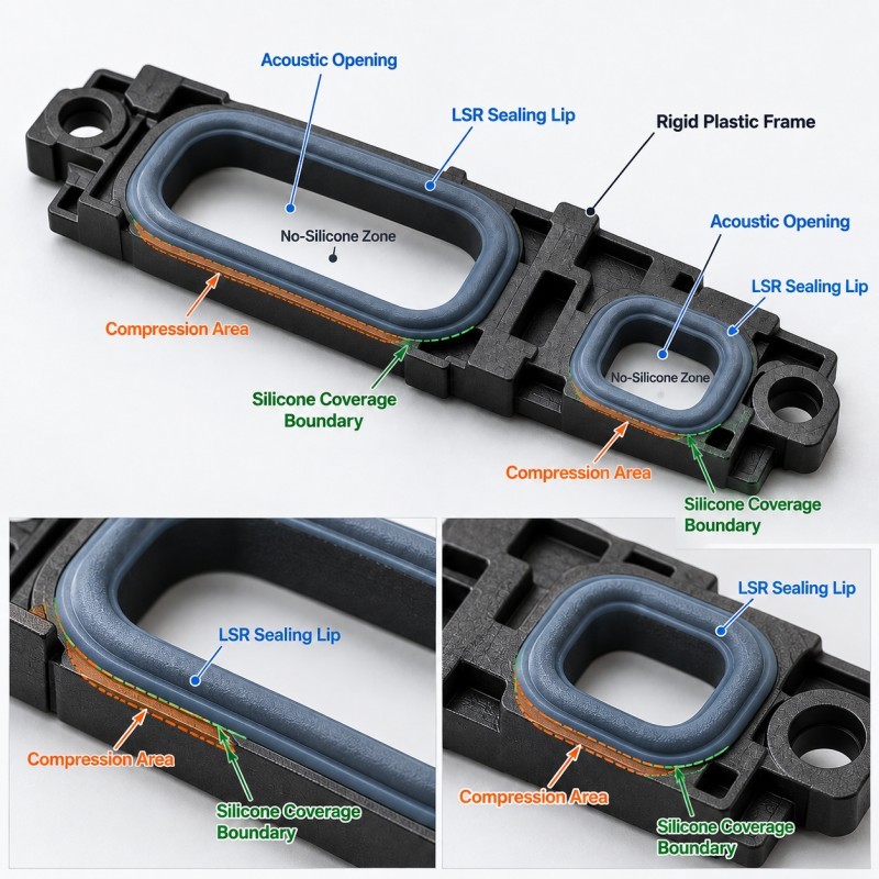
The center of the structure may need to remain completely open while silicone forms a continuous seal around its perimeter.
Possible problems include:
• Silicone entering the speaker opening
• Flash partially covering a microphone port
• Port misalignment after insert molding
• Uneven compression around the acoustic opening
• Leakage between adjacent acoustic channels
• Silicone interfering with a mesh mounting area
• Housing deformation changing the final channel geometry
This means engineers must treat the sealing area and the sound path as two separate functional zones.
A design that improves sealing but restricts the acoustic opening is not a successful acoustic interface.
1. Define the Sound Path as a Critical No-Silicone Zone
The first step is to identify every surface where silicone must not remain.
For a speaker or microphone interface, these areas may include:
• Speaker sound opening
• Microphone inlet
• Acoustic channel
• Mesh mounting area
• Pressure-equalization opening
• Alignment datum
• Electrical or assembly interface
These areas should be treated as controlled no-silicone zones rather than ordinary cosmetic surfaces.
The drawing should clearly define:
• Opening diameter or outline
• Silicone coverage boundary
• Minimum clear acoustic area
• Critical shut-off surface
• Permitted flash condition
• Mesh or membrane clearance
Even a thin silicone membrane across part of an acoustic opening can change the functional condition of the interface.
The sound path should therefore be protected by mold design and dimensional control rather than relying on manual trimming after molding.
2. Port Alignment Must Be Controlled Through the Complete Assembly
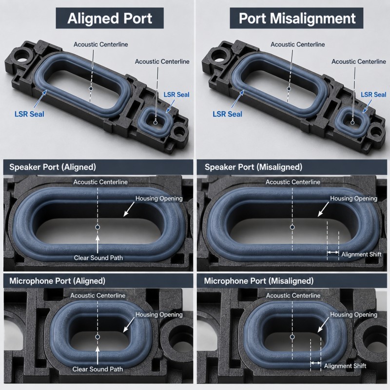
The molded silicone opening cannot be evaluated independently from the final device housing.
The actual acoustic path may involve:
• Internal speaker or microphone module
• Plastic acoustic frame
• LSR sealing structure
• Acoustic mesh or membrane
• External housing opening
• Internal acoustic channel
These features need to align after assembly.
A small offset may cause:
• Partial sound-path restriction
• Uneven sealing width
• Local silicone interference
• Assembly stress
• Misaligned mesh support
• Increased leakage around one side of the port
The critical dimensions should therefore reference stable datums on the rigid plastic frame and final housing wherever possible.
During validation, engineers should compare the complete assembled alignment rather than inspecting only the loose overmolded frame.
3. Silicone Over Plastic Helps Keep the Seal Attached to the Acoustic Frame
Many acoustic sealing frames use a rigid plastic carrier to establish port position and assembly geometry.
A silicone over plastic structure can integrate the flexible sealing lip directly with that rigid frame.
Depending on the real product architecture, the silicone may form:
• A perimeter sealing lip
• A compression edge
• A local vibration cushion
• A wall between adjacent ports
• A housing-contact seal
• A protected transition around the acoustic opening
The plastic insert provides dimensional support while the silicone provides controlled deformation at the mating interface.
However, the plastic material, heat resistance, warpage, bonding strategy, insert tolerance and molding conditions must all be reviewed before tooling.
The silicone should not be used to compensate for an unstable plastic frame.
4. Compression Must Seal Around the Port Without Deforming It
The acoustic sealing lip normally works by controlled compression against the mating housing, module or frame.
Too little compression may create a leakage path.
Too much compression may:
• Distort the silicone opening
• Push the seal into the sound path
• Increase assembly force
• Roll a thin sealing lip
• Deform the plastic acoustic frame
• Change the intended interface geometry
The design should therefore evaluate:
• Free seal height
• Compressed assembly gap
• Sealing width
• Silicone hardness
• Plastic support underneath the seal
• Housing flatness
• Assembly stops
• Tolerance stack-up
A successful seal should maintain contact around the complete perimeter while preserving the intended acoustic opening.
More compression is not automatically better.
5. Mold Shut-Off Must Protect the Acoustic Opening From LSR Flash
Liquid silicone can enter very small gaps, which makes acoustic openings particularly sensitive to mold shut-off quality.
During LSR injection molding, the mold must contain silicone around the sealing perimeter while preventing it from entering the center sound channel.
The shut-off condition depends on:
• Plastic-frame dimensions
• Insert position
• Opening geometry
• Mold-fit accuracy
• Parting-line location
• Tool wear
• Venting
• Injection conditions
Flash around the outside of a hidden sealing edge may sometimes be mainly cosmetic.
Flash extending into a microphone or speaker opening can become functional because it changes the clear sound-path geometry.
The acoustic opening should therefore have a defined inspection requirement rather than being evaluated only through general appearance inspection.
6. Insert Positioning Controls Both Seal Geometry and Port Size
The plastic acoustic frame must remain accurately positioned throughout mold closing, silicone filling, curing and demolding.
If the insert shifts, the result may include:
• Off-center acoustic opening
• Uneven silicone thickness
• Different sealing width around the port
• Flash on one side of the sound channel
• Exposed plastic in the sealing area
• Misalignment with the device housing
For small microphone ports, even a visually minor position shift may represent a large percentage of the available opening.
The mold should therefore locate the rigid frame from stable surfaces that do not damage critical acoustic or assembly features.
For multi-cavity production, port dimensions and silicone boundaries should be checked by cavity during tooling validation.
7. Adjacent Speaker and Microphone Ports May Need Acoustic Isolation
Some compact electronic assemblies contain more than one acoustic opening in a small area.
The sealing frame may need to separate:
• Speaker and microphone channels
• Primary and secondary microphone ports
• Acoustic and pressure-equalization paths
• Adjacent internal cavities
A silicone wall or local sealing barrier may help isolate these regions, but it must be supported by the rigid frame and correctly compressed after assembly.
Potential failure modes include:
• Cross-leakage between channels
• Incomplete silicone wall formation
• Wall distortion during assembly
• Flash entering one of the openings
• Seal displacement caused by housing tolerance
The exact acoustic-channel architecture should be confirmed by the customer's acoustic engineering team.
The overmolded sealing frame should reproduce the required separation without independently redefining the customer's acoustic design.
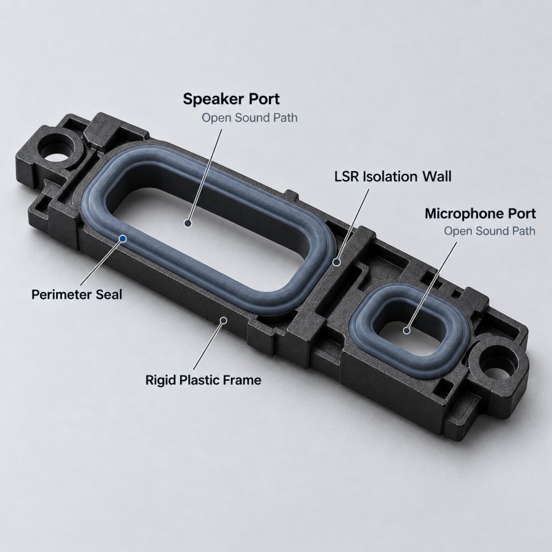
8. Mesh and Membrane Mounting Areas Must Remain Clean and Dimensionally Stable
Some acoustic assemblies use mesh, membranes or other customer-specified acoustic elements after the LSR overmolding process.
If the acoustic frame includes a mounting surface for those components, the area may need to remain:
• Flat
• Clean
• Free of silicone flash
• Dimensionally controlled
• Free of oil or mold contamination
• Correctly aligned with the sound opening
The silicone coverage boundary should stop before the reserved mounting surface unless the actual assembly requires otherwise.
An uncontrolled silicone edge may interfere with later adhesive placement, mesh seating or assembly inspection.
The 2D drawing should therefore identify not only the acoustic opening but also any surrounding keep-out or secondary assembly zone.
9. Silicone Hardness and Lip Geometry Should Be Evaluated Together
Selecting a softer silicone does not automatically create a better acoustic seal.
Seal behavior depends on both material hardness and geometry.
Important variables include:
• Sealing-lip height
• Sealing-lip width
• Wall thickness
• Contact area
• Compression direction
• Plastic-frame stiffness
• Mating gap
• Assembly force
A thin lip made from a relatively harder silicone may still deform easily.
A thick section made from a softer silicone may create more assembly resistance than expected.
The final selection should therefore be validated using the real acoustic frame and mating housing rather than approving hardness from a material sample alone.
10. Waterproof Sealing and Acoustic Performance Must Be Validated Separately
A speaker or microphone sealing frame can pass a leakage test and still require further acoustic validation.
Likewise, an acoustically acceptable opening does not automatically prove environmental sealing.
These are related but different functions.
Depending on the customer project, validation may include:
• Dimensional inspection
• Acoustic-port clearance inspection
• Silicone-coverage inspection
• Flash inspection
• Insert-position measurement
• Compression verification
• Housing assembly test
• Air-leak or pressure-decay testing
• Water or environmental sealing testing
• Thermal cycling
• Drop or vibration testing
• Acoustic performance testing on the finished module
SiliconePlus manufactures the custom sealing frame and overmolded structure.
The final acoustic response, speaker output, microphone sensitivity and complete device performance should be validated by the customer using the actual acoustic module and finished assembly.
| Design Item | Engineering Question | Main Risk | What to Control |
Sound path | Which opening must stay completely clear? | Silicone blockage | Defined no-silicone zone |
Port alignment | Do module, frame and housing openings align? | Restricted acoustic path | Stable datums and assembly check |
Seal compression | Is compression continuous but controlled? | Leakage or port distortion | Seal height + assembly gap |
Mold shut-off | Can LSR be stopped around the opening? | Flash inside sound channel | Insert tolerance + tooling fit |
Insert position | Can the rigid acoustic frame move? | Off-center port | Stable mold locating |
| Channel isolation | Must adjacent ports remain separated? | Cross-leakage | Silicone isolation wall |
| Mesh area | Must a mounting surface remain clean? | Mesh or adhesive interference | Keep-out boundary |
| Validation | Are sealing and acoustic tests both defined? | One function passes, another fails | Complete device validation |
When Is an Integrated LSR Acoustic Sealing Frame Worth Considering?
An integrated sealing frame may be worth evaluating when a speaker or microphone interface requires a repeatable silicone seal around a rigid acoustic opening.
Typical applications may include:
• Smartphones
• Tablets
• Smart watches
• Wearable electronics
• Portable communication devices
• Rugged handheld terminals
• Monitoring electronics
• Compact industrial devices
• Personal-care electronics
Compared with a loose gasket, an integrated frame can keep the silicone sealing geometry attached to the rigid carrier during handling and assembly.
However, integrated overmolding is not automatically better for every acoustic design.
The real plastic frame, port geometry, mesh arrangement, assembly method and production volume should be reviewed first.
SiliconePlus manufactures custom LSR overmolded speaker and microphone sealing frames using plastic acoustic frames or customer-specific housing inserts, with the silicone forming the perimeter seal, compression edge or isolation structure while the acoustic opening remains clear.
What Information Should Be Provided Before Tooling?
For a custom speaker or microphone sealing-frame project, provide as much of the following information as possible:
• 2D acoustic-frame drawing
• 3D CAD file
• Plastic material and grade
• Speaker or microphone opening dimensions
• Required silicone coverage area
• Required clear sound-path area
• Mesh or membrane mounting area
• Silicone hardness requirement
• Final housing drawing
• Assembly gap
• Compression requirement
• Environmental sealing requirement
• Cosmetic requirements
• Inspection standard
• Expected production quantity
• Annual volume forecast
If possible, provide the complete surrounding assembly rather than only the loose acoustic frame.
This helps the tooling team review the real sound path, mating surface, seal compression and port alignment before mold development.
How SiliconePlus Supports Acoustic Sealing Frame Projects
SiliconePlus supports custom speaker and microphone silicone sealing projects from engineering review through tooling, sampling and mass production.
Project review can include:
• Plastic acoustic-frame structure
• Sound-path keep-out area
• Silicone coverage boundary
• Port alignment
• Sealing-lip geometry
• Mold shut-off feasibility
• Insert positioning
• Gate and venting discussion
• Mesh mounting clearance
• Flash-sensitive areas
• Dimensional inspection
• Assembly and leakage validation
• Pilot-production verification
The objective is to create a repeatable silicone sealing interface around the acoustic opening without turning the silicone itself into an uncontrolled obstruction inside the sound path.
FAQ
Can LSR Be Molded Directly Around a Speaker or Microphone Opening?
Yes, when the rigid frame, opening geometry, shut-off surfaces and insert positioning support precision overmolding. The sound path itself must remain open and free of silicone unless the customer's design specifically requires another structure.
Can Silicone Flash Affect Speaker or Microphone Performance?
Yes. Flash that extends into an acoustic opening can reduce the clear sound-path area or interfere with a mesh or assembly surface. Critical openings should therefore have defined flash and inspection requirements.
Does a Waterproof Speaker Seal Guarantee Acoustic Performance?
No. Environmental sealing and acoustic performance are different validation requirements. Final acoustic performance should be tested with the actual speaker or microphone module and finished device assembly.
Can One LSR Frame Seal Both a Speaker and Microphone Port?
Potentially yes, if the frame geometry provides separate controlled sealing paths and the customer's acoustic design allows both interfaces to be integrated. Channel isolation, compression and port alignment must be validated.
Conclusion
LSR speaker and microphone sealing frames must protect the acoustic interface without obstructing the acoustic function.
A reliable design should coordinate:
• Sound-path keep-out zones
• Port alignment
• Silicone coverage
• Seal compression
• Mold shut-off
• Insert positioning
• Channel isolation
• Mesh mounting areas
• Silicone hardness and geometry
• Environmental and acoustic validation
The key design principle is simple:
The silicone should seal around the sound path, not become part of an uncontrolled blockage inside it.
These requirements are easiest to control when the acoustic opening, plastic carrier, silicone boundary and final housing are reviewed together before tooling.
Developing a Speaker or Microphone Sealing Frame?
If you are developing a custom speaker, microphone or acoustic-interface sealing frame, send your 2D/3D drawing, plastic material, acoustic opening dimensions, silicone coverage requirement, final housing structure and estimated production quantity to our engineering team.
You can contact SiliconePlus to review the acoustic sealing structure, silicone overmolding feasibility, tooling concept and validation requirements before mold development.