How Should LSR Overmolding Be Designed Around Metal Pins and Electrical Terminals?
Answer Excerpt
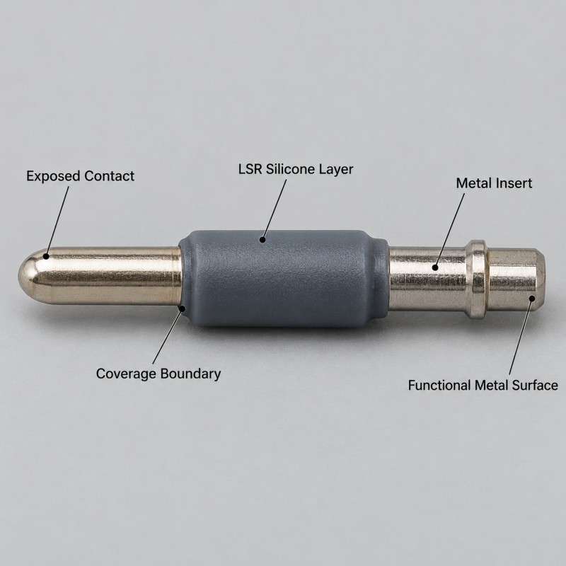
LSR overmolding around a metal pin or electrical terminal should cover only the area that needs insulation, sealing, protection or mechanical support while keeping the required conductive, welding, threaded and locating surfaces exposed.
A reliable silicone over metal design should control:
• Metal material and surface condition
• Exposed electrical contact length
• Silicone coverage boundary
• Insert position and angle
• Mold shut-off around the metal
• Silicone wall thickness
• Bonding or mechanical retention
• Flash around functional metal areas
• Assembly and electrical-function requirements
• Production inspection
The goal is not to cover as much metal as possible.
The goal is to create a repeatable silicone function around the correct section of the metal insert without interfering with the reason the metal component exists in the first place.
What Functions Can LSR Provide Around a Metal Pin or Terminal?
A metal pin or terminal may need silicone for several different reasons.
Depending on the actual component, the molded silicone section may provide:
• Local electrical insulation
• Moisture protection
• Dust protection
• Localized sealing
• Vibration cushioning
• Mechanical support
• Controlled spacing
• Soft protection around a rigid transition
• Positioning inside another housing
These functions should be separated during the engineering review.
For example, a silicone insulation band does not automatically create a waterproof seal.
A silicone sealing collar does not automatically provide sufficient mechanical retention.
A protective silicone section should also not be assumed to provide a specific electrical rating unless that requirement has been designed and validated for the finished assembly.
The exact silicone geometry should therefore be based on the real function required around the metal component.
1. Define the Exposed Metal Area Before Designing the Silicone
Before LSR injection molding is considered, the drawing should clearly identify which sections of the metal pin must remain exposed.
These may include:
• Electrical mating contacts
• Conductive surfaces
• Welding or soldering areas
• Threaded sections
• Press-fit regions
• Precision locating surfaces
• Sensor-contact areas
• Mechanical mounting features
The silicone termination line should be dimensioned from stable metal datums wherever possible.
A note such as “cover this area with silicone” is often not precise enough.
The drawing should show:
• Where silicone starts
• Where silicone stops
• Required exposed length
• Coverage tolerance
• Critical contact surfaces
• Surfaces where silicone flash is not permitted
This makes the coverage boundary measurable during sampling and mass production.
2. Small Metal Pins Need Stable Positioning During Molding
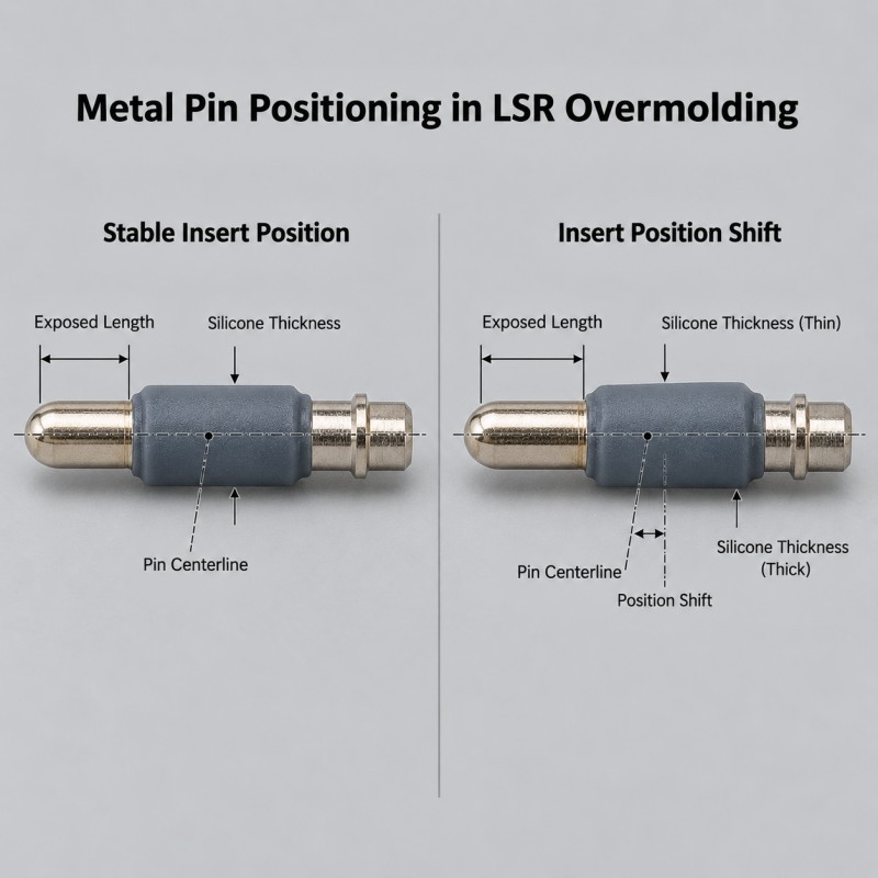
A thin metal pin can be much harder to locate than a large rigid insert.
During molding, the pin must remain stable in:
• Axial position
• Radial position
• Angle
• Rotation, where orientation matters
• Exposed length
• Height inside the mold
If the pin shifts, possible results include:
• Uneven silicone thickness
• Incorrect exposed contact length
• Off-center insulation
• Unstable seal geometry
• Flash around one side
• Different final dimensions
• Assembly interference
The locating method should use metal features that are sufficiently rigid and repeatable.
A fragile electrical contact or precision functional tip should not become the primary clamping surface unless the real design allows it.
For multi-cavity tooling, pin position should also be compared cavity by cavity instead of assuming every insert nest behaves identically.
3. Metal Surface Condition Must Be Controlled Before Overmolding
The LSR contacts the real surface of the metal insert, not only the metal name written on the drawing.
The incoming metal may contain:
• Stamping oil
• Machining coolant
• Fingerprints
• Oxidation
• Plating variation
• Polishing residue
• Burrs
• Dust
• Cleaning-agent residue
• Packaging contamination
The project should define the actual metal grade and surface condition that will enter production.
If the metal is plated or coated, the silicone is interacting with that surface rather than directly with the base metal.
Metal insert preparation should therefore be treated as part of the manufacturing specification when bonding or interface consistency is important.
4. Electrical Contacts Must Remain Controlled No-Silicone Zones
An electrical terminal normally contains at least one area where silicone must not remain.
Examples include:
• Mating contacts
• Connector contact blades
• Probe tips
• Welding surfaces
• Soldering regions
• Grounding surfaces
• Test-contact points
These areas should be treated as functional no-silicone zones rather than ordinary cosmetic boundaries.
A thin silicone film that looks insignificant under normal visual inspection may still cause:
• Poor electrical contact
• Increased insertion interference
• Welding difficulty
• Assembly failure
• Unstable testing
• Additional manual cleaning or trimming
The no-silicone boundary should therefore be controlled by the insert geometry, mold shut-off and inspection plan.
Manual trimming should not be the primary method for recovering a critical conductive surface after molding.
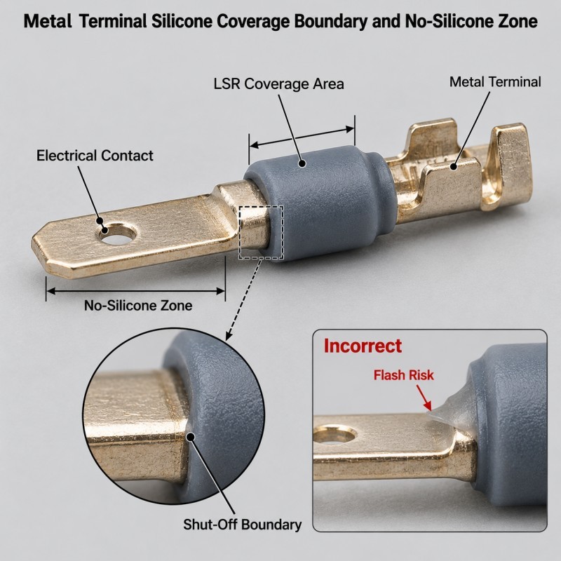
5. Mold Shut-Off Becomes Critical Around Small Metal Diameters
Liquid silicone can enter very small uncontrolled gaps.
This creates a challenge where the mold needs to seal directly around a small pin, terminal or probe.
The shut-off condition depends on:
• Pin diameter tolerance
• Pin straightness
• Insert position
• Metal surface quality
• Mold-fit condition
• Wear over repeated cycles
• Parting-line location
• Injection conditions
If the pin diameter changes between incoming lots, the same mold shut-off may not perform identically.
A loose condition can create silicone flash around the metal.
An excessively aggressive shut-off can mark, bend or damage a delicate insert.
For small electrical inserts, tooling should therefore balance silicone containment with protection of the metal component itself.
6. Bonding Alone Is Not Always the Only Retention Strategy
Some projects require the silicone to remain firmly attached to the metal during pulling, bending, assembly or environmental testing.
Depending on the actual metal and application, retention may involve:
• Material adhesion
• Surface treatment
• Primer-assisted bonding
• Circumferential coverage
• Through-holes
• Grooves
• Undercuts
• Local wraparound structures
• A validated combination of chemical and mechanical retention
Mechanical locking features can provide a physical anchor where the metal geometry permits them.
However, retention features should not be added automatically.
A hole or slot can weaken a thin terminal.
A sharp edge can cut the silicone.
A deep locking feature can trap air or create filling problems.
The correct retention structure should resist the actual load direction without damaging the electrical or mechanical function of the metal insert.
7. Silicone Wall Thickness Should Transition Gradually Around the Metal
The transition from rigid metal to flexible silicone is often a high-stress area.
Risk increases when the silicone changes abruptly from a thick section to a very thin edge around the metal.
Possible problems include:
• Edge peeling
• Local tearing
• Stress concentration
• Uneven filling
• Visible sink or surface variation
• Damage during demolding
• Cracking after repeated mechanical loading
The design should provide a controlled transition where space permits.
Sharp metal corners and burrs should also be avoided in areas directly underneath flexible silicone.
The final geometry should be reviewed according to:
• Silicone hardness
• Metal edge condition
• Expected bending direction
• Pulling force
• Assembly load
• Thermal movement
• Demolding direction
The objective is to prevent the silicone edge from becoming an uncontrolled peel-start location.
8. Gate and Flow Direction Should Not Push the Metal Insert Out of Position
A correctly loaded metal terminal can still move after silicone begins to enter the cavity.
Incoming LSR creates pressure around the insert.
If the gate directs material toward an unsupported section of a thin pin, the insert may:
• Deflect
• Tilt
• Move axially
• Change exposed length
• Create uneven silicone coverage
Gate position should therefore be reviewed together with insert support.
The silicone should fill the intended region without using the metal terminal as an uncontrolled flow obstacle.
For circumferential insulation bands or sealing collars, flow should also reach the complete circumference without trapping air behind the insert.
Gate location, vent position and final-fill area should be evaluated as one system.
9. Flash at the Metal Boundary Is a Functional Defect, Not Only a Cosmetic Issue
Flash around an ordinary hidden silicone edge may sometimes be mainly cosmetic.
Flash around a metal contact can be functional.
It may affect:
• Electrical mating
• Insertion force
• Welding
• Thread engagement
• Probe contact
• Dimensional inspection
• Assembly clearance
The drawing should therefore identify critical flash-free or tightly controlled metal boundaries.
Inspection may require more than a general visual check.
Depending on the component, suitable methods can include:
• Magnified visual inspection
• Optical measurement
• Go/no-go assembly verification
• Exposed-length measurement
• Contact-area inspection
• Electrical-function testing by the customer or agreed process
Acceptance standards should be agreed before mass production.
10. Validate the Complete Metal-Silicone Interface Before Mass Production
A visually acceptable overmolded metal pin is not automatically production-ready.
Validation should match the actual part function.
Depending on the project, engineers may review:
• Metal insert dimensions before molding
• Exposed contact length
• Silicone coverage position
• Silicone thickness
• Concentricity or alignment
• Flash around critical metal areas
• Bonding or retention
• Pull or peel performance
• Assembly fit
• Sealing performance
• Electrical contact exposure
• Thermal cycling
• Vibration
• Pilot-production repeatability
The exact test plan should be defined by the customer's end-use requirements.
A local silicone insulation component does not automatically establish the electrical safety, waterproof rating or final system performance of the complete product.
Those requirements must be validated on the appropriate finished assembly.
| Design Item | Engineering Question | Main Risk | What to Control |
Exposed metal area | Which surfaces must remain conductive or accessible? | Silicone on contact area | Dimensioned coverage boundary |
Insert position | Can the pin shift, tilt or rotate? | Uneven silicone / wrong exposed length | Stable locating references |
Metal surface | What grade, plating and cleanliness enter production? | Bonding inconsistency | Incoming specification |
Mold shut-off | Can the mold seal around the metal without damage? | Flash or bent insert | Pin tolerance + tooling fit |
Retention | How is the silicone held on the metal? | Peeling or movement | Adhesion / mechanical retention |
Wall transition | Is the silicone edge too thin or abrupt? | Tear or edge lifting | Controlled thickness transition |
| Gate and flow | Does incoming LSR push the insert? | Insert movement | Gate + support + venting |
| Contact-zone flash | Can flash affect electrical or mechanical function? | Assembly/contact failure | Defined inspection standard |
| Validation | What must the final assembly survive? | Good sample but failed application | Project-specific testing |
When Should an Integrated LSR Overmolded Metal Pin Be Considered?
An integrated overmolded structure may be worth evaluating when the project requires silicone to remain permanently positioned around a defined section of the metal insert.
Potential applications include:
• Electronic terminals
• Conductive pins
• Sensor probes
• Connector contacts
• Automotive sensing terminals
• Industrial probes
• Metal electrodes
• Precision metal inserts
A separate silicone sleeve or cap may still be suitable for some simple structures.
Integrated overmolding becomes more relevant when:
• Silicone position must remain repeatable
• The coverage boundary is critical
• Loose silicone components can move during assembly
• Several local functions need to be combined
• High-volume insert molding is practical
• Final geometry must remain consistent
SiliconePlus currently offers custom LSR overmolded metal pin components using stainless steel, copper alloy or customer-specified metal inserts, with localized silicone for insulation, sealing, protection or positioning.
What Information Should Be Provided Before Tooling?
For a custom metal-pin or electrical-terminal overmolding project, provide as much of the following information as possible:
• 2D metal insert drawing
• 3D model
• Physical metal sample
• Metal grade
• Plating or coating information
• Required exposed contact area
• Required silicone coverage area
• Silicone hardness requirement
• Required insulation or sealing function
• Assembly method
• Pull or mechanical-load requirement
• Environmental conditions
• Dimensional tolerances
• Inspection requirements
• Estimated order quantity
• Annual production forecast
If the silicone interfaces with another housing after molding, the mating assembly should also be provided whenever possible.
This allows the tooling team to evaluate the actual shut-off, silicone boundary, retention and assembly conditions rather than designing the overmolded insert in isolation.
How SiliconePlus Supports Metal Insert LSR Overmolding
SiliconePlus supports custom silicone-over-metal projects from engineering review through tooling, sampling and mass production.
Project review can include:
• Metal insert structure
• Silicone coverage definition
• Functional exposed zones
• Insert positioning
• Metal surface condition
• Bonding or retention strategy
• Mold shut-off feasibility
• Gate and venting review
• Flash-sensitive areas
• Dimensional inspection
• Assembly validation
• Pilot-production verification
For small pins, terminals and precision metal inserts, the project should be reviewed as a combined metal-silicone component rather than treating the silicone and metal as two unrelated parts.
FAQ
Can LSR Be Molded Around Very Small Metal Pins?
Yes, depending on the pin diameter, rigidity, locating area, required silicone coverage and mold shut-off condition. Small inserts require stable positioning because even minor movement can change exposed length and silicone thickness.
Can the Electrical Contact Area Remain Exposed After Overmolding?
Yes. The silicone coverage boundary can be designed so that electrical contacts, welding areas, threads and other required functional metal surfaces remain exposed. These areas should be defined before tooling.
Does Silicone Always Need to Chemically Bond to the Metal?
Not necessarily. Depending on the application, retention may use material adhesion, surface treatment, primer, mechanical locking or a validated combination of these methods.
How Do You Prevent Silicone Flash Around an Electrical Terminal?
Flash control depends on metal dimensional consistency, insert positioning, mold shut-off, parting-line design, tooling condition and molding parameters. Critical electrical contact boundaries should also have a defined inspection standard.
Conclusion
LSR overmolding around metal pins and electrical terminals requires more than placing a metal insert into a silicone mold.
The metal and silicone must be designed as one functional component.
A reliable design should coordinate:
• Exposed electrical areas
• Silicone coverage boundaries
• Insert positioning
• Metal surface condition
• Mold shut-off
• Retention strategy
• Silicone wall transitions
• Gate and flow direction
• Flash control
• Final inspection and validation
The best time to define these requirements is before tooling.
Once the coverage boundary, metal datum, retention structure and critical functional zones are established, the mold and inspection plan can be developed around the real product requirement.
Developing a Metal Pin or Electrical Terminal Overmolding Project?
If you are developing a custom metal pin, electrical terminal, sensor probe or conductive insert that requires localized silicone insulation, sealing or protection, send your 2D/3D drawing, metal material, surface information, required silicone coverage, exposed functional areas and estimated production quantity to our engineering team.
You can contact SiliconePlus to review the metal insert, silicone coverage boundary, LSR overmolding feasibility, tooling concept and validation requirements before mold development.