How Should Silicone Seals Be Designed for Liquid Cooling Pump Housings and Valve Interfaces?
Answer Excerpt
A silicone seal around a liquid cooling pump housing or valve interface should be designed around the actual coolant leakage path, assembly direction and service condition rather than selected only by gasket shape.
Reliable sealing requires engineers to coordinate:
• Seal geometry
• Groove dimensions
• Compression range
• Housing flatness
• Fastener or clamp position
• Valve or cover movement
• Coolant compatibility
• Thermal cycling
• Serviceability
• Leak-test requirements
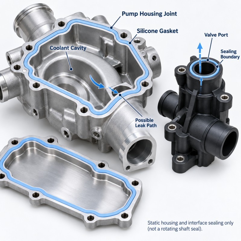
Pump housing and valve seals are usually static interface seals rather than the dynamic shaft seal inside a rotating pump.
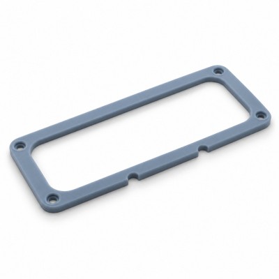
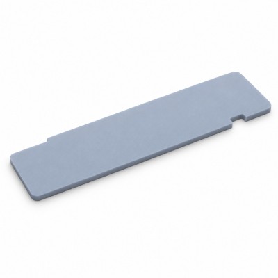
Where the product structure allows it, the silicone may be manufactured as a separate precision molded gasket or integrated onto a suitable plastic or metal carrier through LSR injection molding.
Where Are Silicone Seals Used Around Pumps and Valves?
Liquid cooling systems may contain several pump- and valve-related static interfaces that require controlled sealing.
Depending on the actual architecture, these may include:
• Pump housing-to-cover interfaces
• Removable service covers
• Valve body-to-carrier interfaces
• Valve cartridge surroundings
• Local flange interfaces
• Pump or valve mounting plates
• Sensor or electrical-interface surroundings
• Plastic-to-metal carrier boundaries
These locations should not automatically use the same seal profile.
A pump housing perimeter seal may need to maintain continuous compression around a large boundary.
A valve interface may need a smaller local seal around a controlled fluid passage.
A service cover may need to be opened and reassembled without damaging the seal.
The first design step is therefore to define the exact coolant-containing boundary and the surfaces that must remain dry.
1. Define the Coolant Leakage Path Before Designing the Seal
The seal should interrupt every continuous path between the coolant circuit and the external environment.
Engineers should review:
• Coolant cavity
• Pump housing joint
• Valve port
• Mating flange
• Fastener locations
• Plastic-to-metal transitions
• Assembly gaps
• Adjacent electrical structures
Adding a thicker gasket does not solve a leakage path that bypasses the sealing boundary.
The same principle applies to a liquid cooling connector or manifold interface: the complete coolant path must be understood before the silicone geometry is finalized.
2. Pump Housing Seals Need Continuous Compression
A pump housing seal often follows a perimeter between the main housing and a cover, plate or removable structural component.
The silicone should maintain continuous contact around that perimeter.
Possible leakage risks include:
• Local housing warpage
• Uneven cover flatness
• Fastener spacing variation
• Gasket-height variation
• Corner distortion
• Surface contamination
• Excessive or insufficient compression
Fasteners can create higher local closing force near screw locations and lower force between them.
The housing, cover and gasket should therefore be reviewed as one mechanical system.
This is similar to a cold plate silicone gasket, but the pump housing may introduce different service access, vibration and local geometry requirements.
3. Valve Interfaces Need the Correct Sealing Direction
Valve-related seals can experience different assembly and compression directions.
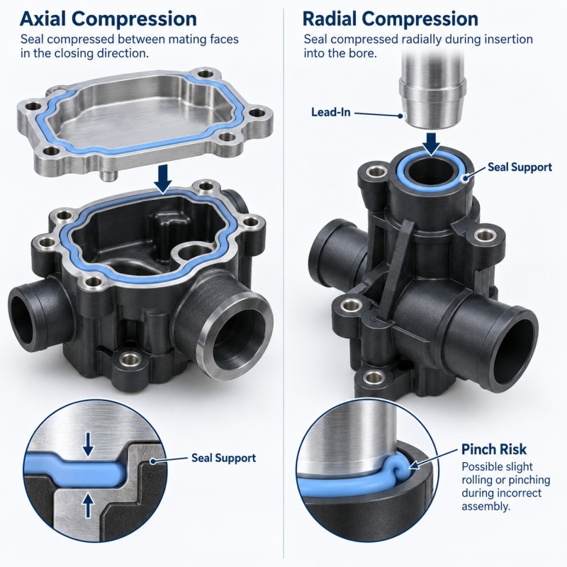
An axial seal is compressed mainly along the closing direction of the housing or valve carrier.
A radial seal is compressed between cylindrical or near-cylindrical mating surfaces.
The correct geometry depends on the real interface.
For an axial seal, engineers should review:
• Final assembly gap
• Seal height
• Contact width
• Surface flatness
• Closing stop
For a radial seal, engineers should review:
• Mating diameter
• Lead-in geometry
• Silicone support
• Insertion direction
• Risk of rolling or cutting
A seal profile designed for axial compression should not automatically be reused for a radial valve interface.
4. Rigid Stops Should Control Final Compression
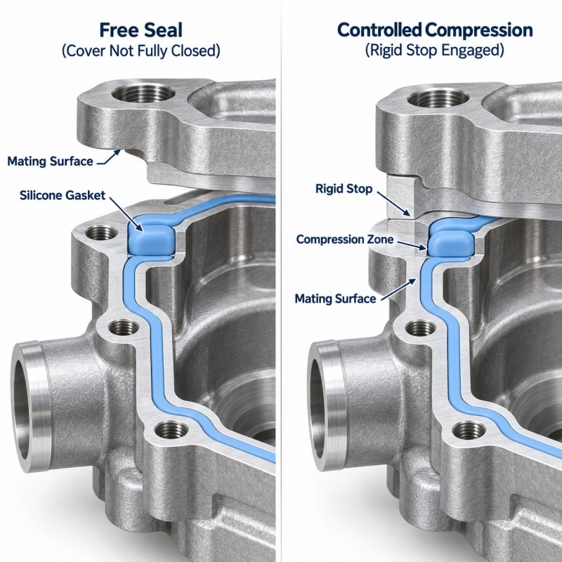
A reliable liquid cooling assembly should not depend only on screw torque or operator feel to determine seal compression.
Where the structure permits it, rigid components should control the final closed position.
Possible compression-control features include:
• Housing shoulders
• Metal stops
• Plastic bosses
• Mating flanges
• Controlled cover gaps
• Defined valve-carrier seating surfaces
The rigid structure reaches the designed stop while the silicone remains within the intended deformation range.
If the structure closes too far, the silicone may flatten, roll or experience unnecessary long-term stress.
If the stop closes too early, the seal may remain under-compressed.
For overmolded sealing structures, compression stops should therefore be reviewed together with seal height and assembly tolerance.
5. Coolant Compatibility Must Be Validated With the Actual Fluid
Liquid cooling systems do not all use the same coolant chemistry.
Depending on the application, the seal may be exposed to different:
• Water-to-glycol ratios
• Corrosion inhibitors
• Additives
• Cleaning fluids
• Operating temperatures
• Pressure conditions
• Exposure durations
The word “silicone” alone does not prove compatibility with every coolant.
The actual material grade should be evaluated against the real coolant formulation and operating condition.
Fluid exposure may affect:
• Volume
• Hardness
• Surface condition
• Mechanical properties
• Compression recovery
• Bonding interface
• Long-term leakage performance
Where reliable compatibility data are not available for the exact combination, the project should perform controlled exposure and functional testing before mass-production approval.
6. Serviceable Interfaces Need Assembly Damage Control
Some pump or valve covers may need to be removed during service.
A seal that performs well during the first factory assembly may be damaged during later disassembly or reassembly.
Possible service-related risks include:
• Seal pinching
• Twisting
• Rolling
• Cutting against a sharp edge
• Stretching during removal
• Dirt on the sealing surface
• Incorrect reinstallation
The design should therefore consider:
• Lead-in geometry
• Gasket retention
• Groove support
• Clear assembly direction
• Easy visual inspection
• Replacement requirements
If the silicone must remain permanently located on a carrier, an integrated LSR overmolded sealing feature may be evaluated where the substrate and assembly structure are suitable.
7. Tolerance Stack-Up Can Create Local Leakage
The seal drawing cannot be evaluated independently from the mating pump or valve components.
Actual compression may depend on:
• Silicone seal height
• Groove depth
• Housing flatness
• Cover thickness
• Valve carrier position
• Fastener location
• Plastic or metal tolerance
• Insert position
• Assembly stop height
Every individual component may pass inspection while the assembled stack still creates too little compression in one location and too much in another.
Worst-case tolerance combinations should therefore be reviewed before tooling.
Critical dimensions should be connected to actual sealing function instead of applying unnecessarily tight tolerances to every silicone feature.
| Engineering Item | What to Review | Main Risk | Validation Focus |
Leakage path | Complete pump or valve boundary | Unsealed bypass path | Full assembly leak test |
Seal compression | Min/max assembly condition | Under- or over-compression | Compression verification |
Housing flatness | Cover and body geometry | Local low contact | Dimensional inspection |
Valve interface | Axial or radial loading | Rolling or cutting | Assembly test |
Coolant compatibility | Actual coolant formulation | Swelling or property change | Fluid exposure |
| Service access | Removal and reassembly | Pinching or damage | Reassembly validation |
| Tolerance stack | Worst-case dimensions | Local leakage | Stack-up review |
| Production control | Repeated parts and assemblies | Good sample but unstable process | Pilot production |
How Should Pump and Valve Seals Be Validated?
The final validation plan should reflect the actual liquid cooling system rather than using a generic waterproof test.
Depending on the project, validation may include:
1. Dimensional inspection.
2. Visual inspection of the sealing path.
3. Assembly-fit verification.
4. Compression confirmation.
5. Pressure-decay or air-leak testing where applicable.
6. Coolant leakage testing with the specified fluid.
7. Thermal cycling.
8. Fluid exposure or aging.
9. Vibration testing where required.
10. Service removal and reassembly testing where relevant.
11. Pilot-production verification.
The test should define the actual pressure, temperature, fluid, duration and allowable leakage criteria required by the customer.
A generic IP rating should not automatically be treated as equivalent to an internal coolant leakage specification.
Separate Silicone Gasket or Integrated LSR Overmolded Seal?
Both approaches can be suitable depending on the real pump or valve structure.
A separate precision molded silicone gasket may be practical when:
• The housing contains a controlled groove
• The seal needs to remain replaceable
• Independent inspection is required
• Service replacement is expected
An integrated LSR overmolded seal may be evaluated when:
• Silicone needs to remain fixed to a plastic or metal carrier
• Several local sealing features can be integrated
• Manual gasket placement creates production risk
• Seal positioning must remain repeatable
The decision should consider tooling, assembly, serviceability, material compatibility and production volume rather than assuming one solution is universally better.
How SiliconePlus Supports Liquid Cooling Sealing Projects
SiliconePlus supports custom silicone sealing and LSR overmolding projects from engineering review through tooling, sampling and mass production.
Project review can include:
• Pump or valve sealing-path analysis
• Silicone gasket geometry review
• Groove and compression review
• Plastic or metal carrier evaluation
• LSR overmolding feasibility
• Mold shut-off review
• Material and coolant-condition discussion
• Dimensional inspection planning
• Leakage-test requirement review
• Pilot-production validation
The objective is to develop a repeatable sealing structure based on the actual pump housing, valve interface, coolant and assembly condition rather than applying a generic gasket design.
FAQ
Can Silicone Be Used With Every Liquid Cooling Coolant?
No. Compatibility depends on the exact silicone grade, coolant formulation, concentration, temperature, pressure and exposure duration. The real material and fluid combination should be validated before production approval.
Is a Pump Housing Seal the Same as a Mechanical Shaft Seal?
No. This article focuses on static silicone sealing interfaces around pump housings, covers, carriers and adjacent valve structures. Dynamic rotating shaft seals have different operating and material requirements.
Can an LSR Seal Be Overmolded Directly Onto a Pump or Valve Carrier?
Potentially, if the plastic or metal carrier, sealing geometry, material compatibility, mold shut-off and service requirements are suitable. The complete structure should be reviewed before tooling.
What Information Is Needed for a Custom Liquid Cooling Seal Quote?
Provide the 2D/3D drawing, carrier material, sealing location, mating geometry, coolant formulation, operating temperature and pressure, leakage requirement, expected production volume and relevant validation conditions.
Conclusion
A reliable liquid cooling pump or valve seal is the result of a controlled sealing system rather than simply choosing a soft gasket material.
Engineers should coordinate:
• Coolant leakage path
• Seal geometry
• Compression direction
• Rigid assembly stops
• Housing tolerances
• Coolant compatibility
• Serviceability
• Thermal exposure
• Leak-test conditions
Where appropriate, both separate molded silicone gaskets and integrated LSR overmolded seals can be evaluated.
The correct solution should be determined from the real housing, valve structure, fluid condition and production requirement before tooling begins.
Developing a Liquid Cooling Pump or Valve Seal?
If you are developing a custom liquid cooling pump housing or valve sealing component, send your 3D drawing, carrier material, sealing interface, coolant information, operating conditions, leakage requirement and expected production quantity to our engineering team.
You can contact SiliconePlus to review silicone gasket geometry, LSR overmolding feasibility, tooling and validation requirements before mold development.