How Should an LSR-Overmolded Silicone Tubing Y-Connector Be Designed to Keep the Fluid Path Open?
Answer Excerpt
An LSR-overmolded silicone tubing Y-connector should be designed around three priorities: an unobstructed internal fluid path, accurately positioned tube ends, and a controlled external overmold around the branch junction. Before tooling, the drawing should define tube inner and outer diameters, branch angle, insertion depth, overmolding length, junction geometry and all areas that must remain free of silicone. The finished assembly should then be inspected and validated against the customer's actual fluid-transfer requirements.
Why Is an Overmolded Silicone Y-Junction Difficult to Design?
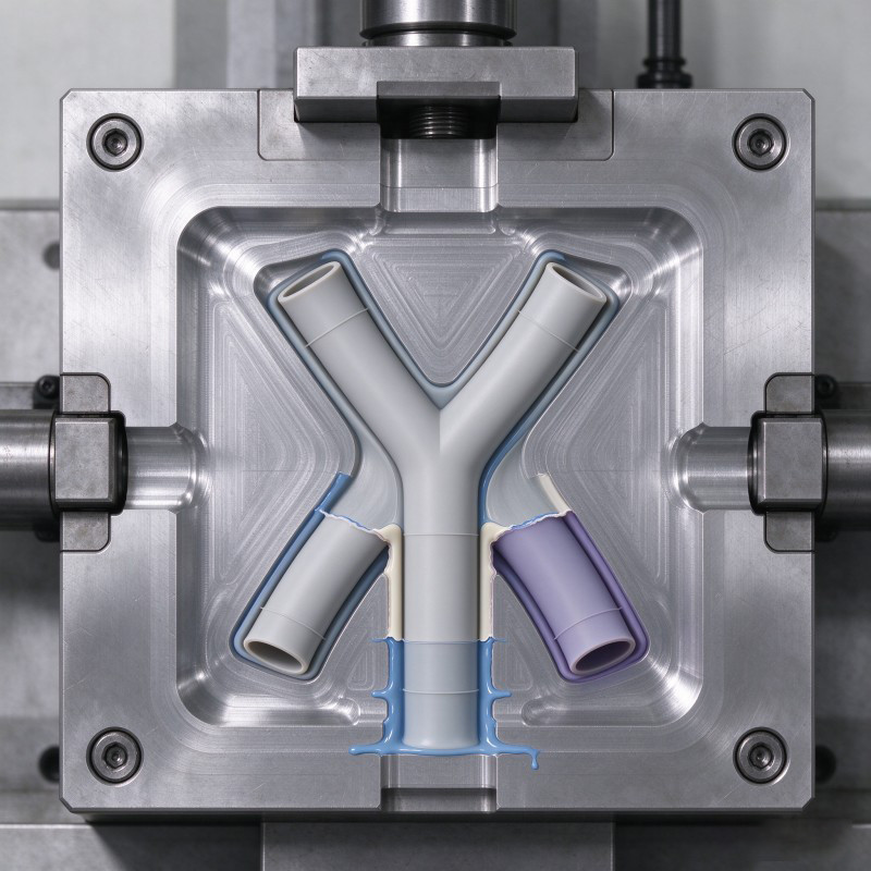
A Y-shaped tubing junction must connect multiple tube branches while preserving the intended internal flow path. In an overmolded design, the external silicone junction is molded around positioned silicone tubes, so the tube locations, mold shut-off areas and internal openings must be considered together.
The central challenge is that the outside of the junction needs enough molded material to form the intended connection, while the inside must remain open. Silicone entering a tube lumen, flash crossing an opening or a tube shifting during molding can create a part that looks acceptable externally but does not match the approved internal geometry.
SiliconePlus lists a custom LSR-overmolded silicone tubing Y-connector for medical and bioprocess fluid-transfer applications. The published product description identifies silicone tubing as the substrate and liquid silicone rubber as the overmolding material. Tube dimensions and branch geometry are customized according to the drawing and project requirements.
The exact configuration, material documentation and application acceptance criteria must be confirmed for each project. A generic Y-connector drawing should not be treated as a universal design for every tubing system.
How Can the Internal Fluid Path Be Kept Open?
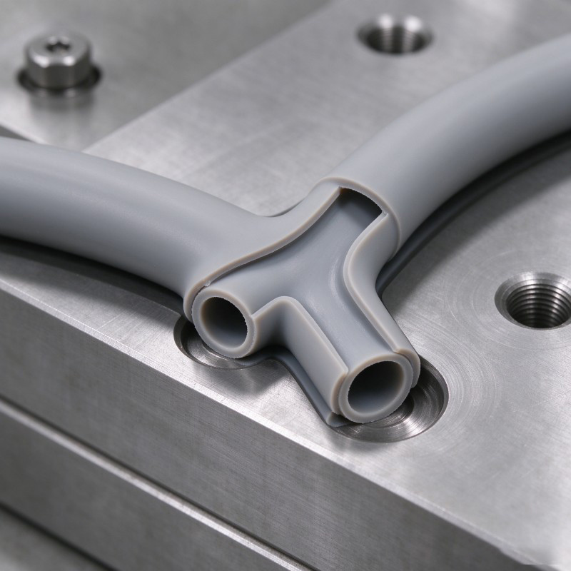
The fluid lumen is a critical no-silicone zone. The design must protect the internal openings of the positioned tubes while allowing the external junction to be molded as intended.
Start by identifying the complete internal flow path in the drawing or 3D model. Show where the individual tube lumens meet, which openings must remain clear and how the intended branch geometry relates to the external overmold.
The tooling concept should then explain how the tube ends will be supported and how silicone flow will be restricted from entering the lumen. Depending on the actual geometry, the review may involve core features, shut-off surfaces, tube support and the position of the tube ends inside the mold.
Do not rely on visual inspection of the outside alone. A smooth exterior does not prove that the internal path is open. Inspection access and a suitable verification method should be agreed before samples are approved.
If the junction includes different tube sizes or a non-standard branch arrangement, the internal transitions require particular attention. The final design should be evaluated using the actual tubing specifications and the customer's flow-path requirements, not an assumed standard internal shape.
Fluid Path Design Review
| Design area | What to define | What to check |
Tube lumen | Inner diameter and required open length | No unintended silicone intrusion or blockage |
Branch intersection | Intended relationship between the tube openings | Internal geometry matches the approved drawing |
Tube-end position | Insertion depth and location references | Tube ends remain in the intended position during molding |
| Mold shut-off | Areas that restrict silicone from entering the lumen | Shut-off concept matches the real tube and mold geometry |
| Inspection access | How internal openings will be checked | The inspection method can identify relevant defects |
| Flow requirements | Customer-defined fluid and system requirements | Finished assembly is evaluated against agreed criteria |
Which Tube and Branch Dimensions Must Be Defined Before Tooling?
A manufacturable Y-junction begins with a clear dimensional definition. The buyer should not provide only an exterior rendering or a nominal tube size when the internal fluid path is functionally important.
At minimum, the design review should identify:
- Tube inner diameter (ID): Defines the intended internal opening and forms part of the fluid-path specification.
- Tube outer diameter (OD): Establishes the external interface around which the overmold must be formed.
- Branch angle: Defines the relationship between the tube branches and the intended assembly layout.
- Insertion depth: Shows how far each tube extends into the junction region.
- Overmolding length: Identifies the external region covered by the molded silicone.
- Junction geometry: Defines the outside profile and transitions between the branches.
- Wall and transition requirements: Establishes the relevant dimensions where the external molded junction changes shape.
- Position references: Provides datums or other references for repeatable tube placement and inspection.
SiliconePlus provides silicone-to-silicone overmolding solutions for custom designs based on drawings, tube samples and application requirements. Where tube dimensions differ between branches, the drawing should identify each tube separately instead of assuming all branches are identical.
The final dimensions must come from the approved design. Do not use generic branch angles, insertion depths or wall thicknesses as substitutes for application-specific engineering decisions.
How Should Tube Positioning and Mold Shut-Off Be Controlled?
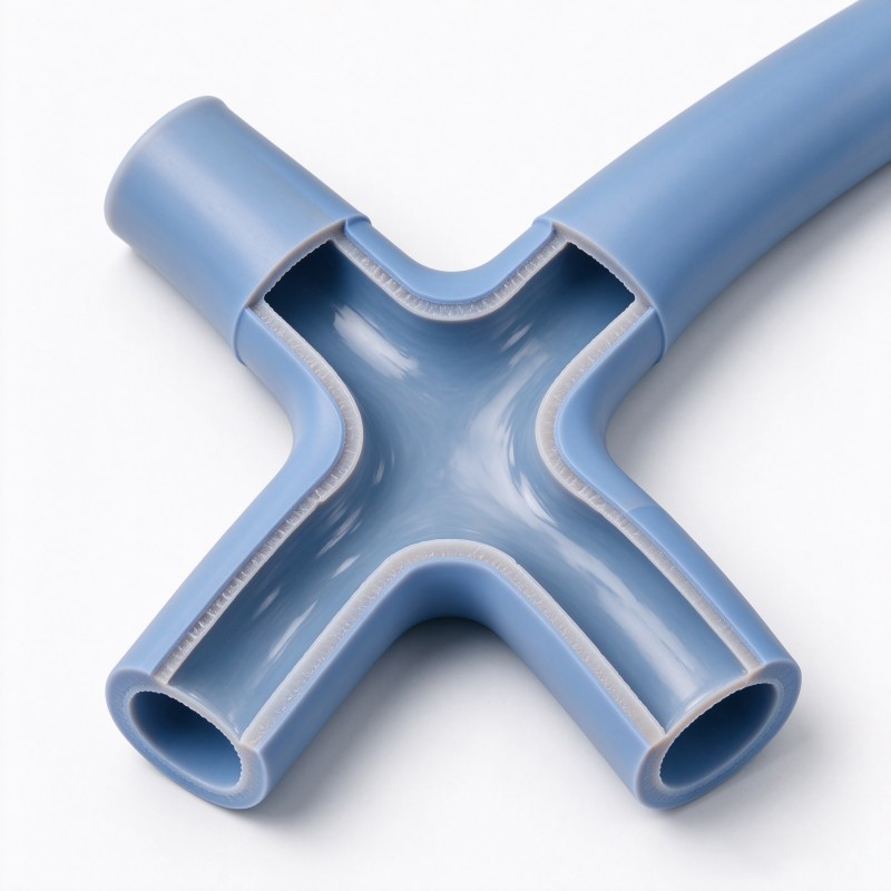
Tube positioning must be repeatable. If the branches move away from their intended locations during mold closing or filling, the finished junction may not match the approved dimensions or internal flow-path geometry.
The mold review should establish how each tube is located, supported and held in position. The support method must suit the actual tube dimensions and flexibility, and it must not damage or unintentionally deform the tubing.
The shut-off design should control the boundary between the external overmold and the openings that must remain clear. The engineering review should also consider the overmolded junction length, branch transitions, gate and venting locations, and how the molded component can be removed without damaging the tube interfaces.
These decisions should be made against the actual 3D geometry and proposed molding process. A shut-off feature that works for one tube size or branch layout may not be appropriate for another.
Before tooling approval, the design team should review the loading sequence, positioning references, potential tube movement, flash-sensitive areas and the inspection method for the critical openings. The purpose is to establish a controllable process rather than depend on visual adjustment during production.
Tooling Risk and Control Review
| Potential risk | Design or tooling control | Inspection focus |
Tube movement | Defined positioning and support features | Branch position and insertion depth |
Silicone entering the lumen | Appropriate core and shut-off strategy | Internal openings and fluid-path clearance |
Flash at tube interfaces | Controlled shut-off surfaces and mold fit | Flash location and effect on function |
| Uneven junction geometry | Drawing-defined external profile and mold layout | Junction dimensions and transitions |
| Tube damage during demolding | Review the removal sequence against tube flexibility | Cuts, tears, distortion or interface damage |
| Inconsistent overmold coverage | Defined coverage boundary and positioning references | Coverage length and location |
How Should Material Compatibility and Application Requirements Be Reviewed?
The tube material and the overmolding material must be reviewed as a combination. The fact that both materials are silicone does not, by itself, establish that the selected materials and process will produce the required interface.
The buyer should identify the tube material specification, the proposed LSR, relevant surface or preparation requirements and any known restrictions on the manufacturing process. The engineering review should determine whether the required interface relies on material bonding, mechanical retention or another validated design approach.
Application conditions must also be documented. For medical or bioprocess projects, requirements such as fluid compatibility, cleanliness, material documentation, biocompatibility and sterilization compatibility should be specified according to the actual use case. These requirements must not be inferred from the product category alone.
SiliconePlus provides silicone mold design capabilities for custom product structures. For a Y-junction, the design review should connect material selection, tube positioning, internal clearance, mold shut-off and the inspection plan into one coherent proposal.
No material compatibility, medical compliance or sterilization claim should be accepted without the relevant documentation and validation for the selected material combination and finished assembly.
How Should a Finished Y-Connector Be Inspected and Validated?
Validation should address both the molded exterior and the internal fluid path. A part that looks smooth may still contain a blocked opening, misplaced tube or internal defect that cannot be confirmed from an external view.
A project-specific inspection plan may include the following:
- Dimensional inspection: Verify tube ID and OD where applicable, branch angle, insertion depth, overmolding length and other drawing-defined dimensions.
- Visual inspection: Check the external junction for incomplete filling, flash, cuts, tears, surface defects and unintended deformation.
- Fluid-path verification: Confirm that the required openings remain clear using an agreed inspection method.
- Interface evaluation: Assess the tube-to-overmold junction according to the specified retention or bonding requirements.
- Assembly evaluation: Check the finished connector in the intended tubing arrangement where the mating configuration is available.
- Functional testing: Define any flow, leakage, pressure, cycling or other application-specific tests that are required by the customer.
Test methods and acceptance criteria must be established before samples are approved. For example, a leakage test requires an agreed test setup, medium, conditions and pass/fail criteria; these should not be invented by the supplier or copied from an unrelated application.
The selected liquid silicone injection molding process should be evaluated against the actual tube geometry, material combination and tooling concept. Sample inspection and validation can support component approval, but the performance of the complete fluid-transfer system must be established separately according to the customer's requirements.
Sample Approval Checklist
| Inspection area | Acceptance basis | Evidence to retain |
External dimensions | Approved drawing and defined measurement method | Dimensional inspection record |
Branch geometry | Approved branch angle and position references | Measurement or fixture inspection record |
Tube interface | Drawing-defined insertion depth and coverage | Visual and dimensional inspection record |
Internal fluid path | Approved opening and lumen requirements | Agreed internal inspection evidence |
| Surface condition | Defined appearance and defect criteria | Visual inspection record |
| Functional validation | Customer-defined test method and acceptance limits | Test procedure and recorded results |
| Material requirements | Approved material specification and documentation | Material records and applicable supporting documents |
What Should Buyers Include in an RFQ?
A complete RFQ helps the manufacturer evaluate the junction design, identify missing information and prepare a quotation based on the actual project requirements.
For a custom LSR-overmolded silicone tubing Y-connector, buyers should provide:
1. 2D drawing and 3D CAD: Show the overall junction, internal flow path, branch layout and critical interfaces.
2. Tube specifications: Identify the material, inner diameter, outer diameter and relevant dimensional tolerances for each branch.
3. Branch geometry: Define branch angle, insertion depth, junction length and the required external overmolding coverage.
4. Material requirements: Specify the proposed tube and LSR materials, including any documentation or compatibility requirements.
5. Application conditions: Describe the intended fluid, operating environment and other conditions relevant to the component.
6. Functional acceptance criteria: Define required inspection, flow, leakage or other tests and their acceptance limits.
7. Regulatory and cleanliness requirements: Where relevant, identify the actual medical, bioprocess, cleanliness or sterilization requirements.
8. Commercial information: Provide prototype needs, estimated production quantity, forecast and target timing.
If some details have not been finalized, mark them as open items for engineering review. This allows the supplier and buyer to discuss feasibility before tooling decisions are locked in.
Frequently Asked Question
Can LSR Be Overmolded Around Existing Silicone Tubes?
A silicone-to-silicone overmolded junction can be evaluated as a custom manufacturing process. Feasibility depends on the tube material, selected LSR, interface design, tube positioning and molding conditions. The finished interface must be evaluated against the project's requirements.
How Can Silicone Be Prevented from Blocking the Tube Lumen?
The internal fluid path must be identified as a critical no-silicone area. The tooling concept should control tube position and silicone flow using appropriate support and shut-off features. An agreed inspection method should verify that the required openings remain clear.
Can the Branch Angle and Tube Diameters Be Customized?
The SiliconePlus product page identifies branch geometry and tube sizes as customizable according to the drawing. The buyer should specify each tube's inner and outer diameters, branch angle and relevant junction dimensions in the approved design.
Does an Integrated Y-Junction Guarantee Better Flow?
No. An integrated junction may reduce separate fittings and secondary assembly steps, but flow performance depends on the complete internal geometry, fluid conditions and system configuration. Functional performance must be validated against the customer's requirements.
Does a Medical or Bioprocess Application Automatically Mean the Connector Is Certified?
No. The application category alone does not establish regulatory compliance, biocompatibility, cleanliness or sterilization compatibility. These requirements must be specified and supported by appropriate material documentation and application-specific validation.
Conclusion
An LSR-overmolded silicone tubing Y-connector should be designed around its internal fluid path, tube positioning and external junction geometry as one integrated component.
Before tooling, define tube ID and OD, branch angle, insertion depth, overmolding coverage and all no-silicone areas. Review the material combination, positioning strategy, mold shut-off and inspection method against the actual drawing.
Sample approval should verify both the external molded structure and the required internal openings. Any flow, leakage, durability or regulatory requirements must be defined and validated for the intended application.
For OEM and ODM buyers, supplying complete drawings, tube samples, material information and acceptance criteria early helps the manufacturer evaluate feasibility and quote the appropriate custom solution.
Discuss Your Custom Silicone Tubing Y-Connector Project
Developing a custom silicone tubing junction for medical equipment, laboratory systems or fluid-transfer applications?
SiliconePlus supports custom silicone-to-silicone overmolding projects from design review and tooling development through sampling and agreed production inspection.
Share your 2D drawing, 3D CAD, tube specifications, branch geometry, material requirements and estimated quantity. Our team can review the available information and identify the details needed for a manufacturing quotation.
To discuss your design and manufacturing requirements, contact SiliconePlus for a project review.