How Should an LSR-Overmolded VR Eye Mask Balance Facial Sealing and Lens Clearance?
Answer Excerpt
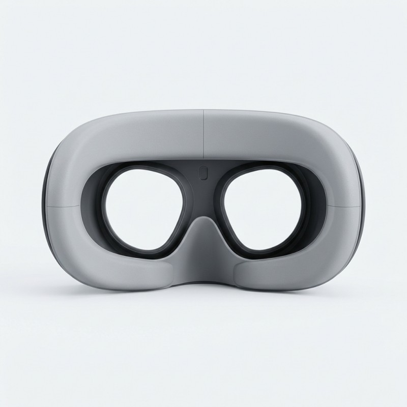
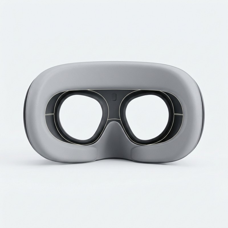
An LSR-overmolded VR eye mask must perform two different jobs without allowing one to compromise the other: its silicone face-contact layer should follow the intended facial sealing path, while the rigid insert and headset structure preserve the required optical reference and lens clearance.
The design should define a continuous contact boundary, controlled silicone compression, an unobstructed optical opening and a stable rigid-to-soft transition.
Final fit must be evaluated in the complete headset assembly against the customer's optical, comfort and sealing requirements. A soft silicone surface alone does not prove continuous facial contact or guarantee that the intended lens clearance is maintained.
Why Does a VR Eye Mask Have Two Different Design Jobs?
A VR eye mask sits between the user's facial contact area and the headset's optical assembly. Its soft silicone layer provides a compliant contact surface, while the rigid plastic structure must maintain the intended mechanical relationship with the headset.
These two functions need to be reviewed separately.
The facial interface must accommodate the intended contact geometry. The optical system, however, needs stable reference surfaces so that the eye opening, lens carrier and other optical features remain in their specified positions.
If the silicone layer is treated as the only dimensional reference, changes in compression or assembly conditions may affect the finished interface.
SiliconePlus lists a custom LSR-overmolded VR eye mask built around precision plastic inserts and a silicone-over-plastic structure. This is a product-specific example of how an integrated silicone contact layer can be developed for wearable equipment.
For related device projects, review our 3C electronics silicone customization solutions.
Which Reference Geometry Should Control Lens Clearance?
The lens clearance should be controlled by the headset's approved optical and mechanical reference geometry, not by an uncontrolled silicone surface.
Before tooling, engineers should identify the relationship between the optical assembly, rigid headset structure, plastic insert and silicone face-contact layer.
A practical reference hierarchy includes:
1. Optical reference: the lens carrier or other approved optical datum defines the required optical position.
2. Headset reference: the chassis and mounting features establish how the eye-mask component fits into the complete device.
3. Insert reference: the rigid plastic insert provides the locating geometry used during overmolding and assembly.
4. Silicone reference: the molded face-contact surface accommodates the intended facial interface within the approved dimensional envelope.
The silicone layer may deform during use. Therefore, it should not be the sole datum for positioning the optical assembly.
Buyers should provide the lens carrier or headset assembly drawing wherever possible. A standalone eye-mask drawing may not contain enough information to evaluate the final lens clearance.
Reference Geometry and Design Responsibility
Reference | What should be defined | Why it matters |
| Optical datum | Lens carrier position and approved optical reference | Establishes the optical relationship |
Headset chassis | Mounting surfaces and assembly references | Controls component installation |
| Rigid plastic insert | Locating features and critical dimensions | Supports repeatable molding and assembly |
| Silicone contact surface | Free-state profile and intended contact boundary | Defines the compliant facial interface |
| Retention system | Relevant fastening or strap arrangement, where applicable | Influences the assembled contact condition |
How Should the Facial Sealing Path Be Defined?
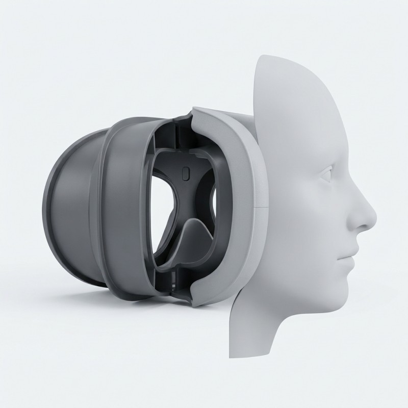
The facial sealing path should be defined from the actual VR eye-mask geometry and the intended user-contact requirements.
It should not be created by simply extending silicone around every available edge of the plastic insert.
During design review, engineers should identify:
- The intended continuous facial contact boundary.
- The beginning and end of the silicone-covered region.
- Areas where the contact profile changes direction.
- Local transitions around the nose bridge or cheek area, where present in the design.
- Areas that must remain rigid or exposed.
- The relationship between the contact surface and the headset's optical opening.
A representative faceform, approved reference sample or other agreed fitting reference can help the team review the intended contact geometry.
The contact boundary should also be reviewed in three dimensions. A two-dimensional outline may not show whether a local transition creates a gap, an abrupt ridge or an unintended interference point.
For projects involving plastic inserts, the proposed structure should be evaluated as a complete plastic with silicone overmolding design rather than treating the silicone layer as a separate accessory.
How Should Local Silicone Compression Be Controlled?
The silicone face-contact layer should be evaluated in its assembled condition, not only by measuring its free-state thickness.
The final contact condition may be influenced by:
- The rigid insert dimensions.
- The silicone profile and local wall thickness.
- The headset mounting geometry.
- The retention or strap arrangement, where applicable.
- The mating structure and its dimensional variation.
- The intended facial contact reference.
Insufficient compression may leave gaps along the intended contact path. Excessive compression may create uncomfortable local contact, distort the silicone profile or cause the material to extend into an area that should remain clear.
For this reason, the design review should identify the nominal assembled condition and the relevant dimensional variation around it.
Where the design includes rigid assembly stops, their relationship with the silicone contact surface should also be reviewed. Do not add a compression stop automatically if the product architecture does not require one.
The appropriate compression range must be established from the actual product geometry, LSR material and customer acceptance criteria. There is no single universal compression value for every VR eye-mask design.
Facial Contact and Compression Review
| Contact area | What to review | Potential concern |
Upper contact region | Profile continuity and assembled gap | Local separation or excessive contact |
Nose bridge area, if present | Transition geometry and available clearance | Local interference or an incomplete contact path |
| Lower contact region | Silicone profile and rigid support | Uneven contact condition |
| Outer perimeter | Coverage boundary and edge transition | Gaps, edge lifting or unintended flash |
| Optical opening boundary | Silicone position under assembly conditions | Material intrusion into the required opening |
How Should the Optical Opening and Lens Keep-Out Zone Be Protected?
The optical opening must be treated as a controlled functional zone during LSR overmolding.
The drawing and CAD model should distinguish between the intended silicone coverage and the areas that must remain clear for the optical assembly.
Depending on the headset architecture, the keep-out definition may include:
- Lens apertures.
- Lens carrier seating surfaces.
- Optical adjustment or movement interfaces.
- Eye-tracking camera openings, where present.
- Other sensors or functional openings, where present.
- Assembly features that must remain accessible.
The mold shut-off and silicone coverage boundary should be designed around these requirements.
Flash, material overflow or an incorrectly positioned insert may affect the opening even when the outer silicone profile looks acceptable.
The optical keep-out zone should therefore be checked on the molded component and again after installation into the headset.
Do not use a generic clearance dimension for every headset. The required opening and lens clearance must come from the customer's optical and mechanical design.
How Should the Rigid-to-Soft Transition Be Designed?
The transition between the rigid plastic carrier and the silicone face-contact layer affects both the finished profile and the manufacturing feasibility of the component.
A poorly controlled transition may create an abrupt ridge, an unnecessarily thin silicone edge or a local area that is difficult to mold and inspect.
The design review should consider:
1. Smooth geometric transitions where the product structure allows.
2. Sufficient silicone coverage at the intended contact boundary.
3. Avoidance of unnecessary sharp edges or knife-thin silicone sections.
4. A suitable bonding land between the selected LSR and plastic substrate.
5. Demolding direction and the possibility of edge damage.
6. The location of the parting line relative to the facial contact surface.
The selected plastic and LSR combination must also be evaluated for the actual application. Chemical bonding should not be assumed simply because the substrate is described as engineering plastic.
The proposed geometry, parting line and demolding strategy should be reviewed through silicone mold design capabilities before tooling is finalized.
How Should LSR Material and Hardness Be Selected?
The silicone material should be selected according to the intended contact behavior, product geometry and application requirements.
A softer material does not automatically create a better VR interface. The final feel and deformation also depend on silicone thickness, support geometry, contact area and assembled compression.
Before selecting the LSR grade, buyers and engineers should review:
- The intended contact and cushioning function.
- The available silicone thickness.
- The required deformation and recovery behavior.
- The rigid substrate material and surface condition.
- The expected cleaning or environmental exposure.
- Any material documentation required by the device manufacturer.
- The required sample and assembly validation.
Material compatibility must be confirmed for the exact plastic grade and LSR system. Requirements for skin contact, biocompatibility or other regulatory documentation should be specified by the device owner and verified for the actual material combination.
For a broader material-selection framework, see our guide to silicone hardness selection for LSR overmolding.
LSR Material Selection Inputs
Input | What should be confirmed | Why it matters |
LSR grade | Exact material specification | Establishes the intended material system |
Hardness | Customer requirement or approved sample reference | Influences deformation and contact feel |
| Silicone thickness | Local geometry and variation | Affects the final interface behavior |
Plastic substrate | Exact plastic grade and surface condition | Determines compatibility and bonding feasibility |
| Contact requirements | Intended contact and cushioning function | Defines material-selection priorities |
| Cleaning and environment | Relevant exposure conditions | Supports project-specific material review |
| Documentation | Required material and compliance records | Supports device-maker qualification |
How Should Mold Design Protect the Facial Contact Surface?
The mold must reproduce the intended silicone profile while keeping the plastic insert correctly positioned.
For a VR eye mask, the facial contact surface is a functional interface rather than a purely cosmetic surface.
The tooling review should consider:
- Insert locating features and repeatable loading.
- The silicone coverage boundary.
- Mold shut-off around the optical keep-out zone.
- Parting-line location relative to the contact surface.
- Venting and the risk of trapped air in the intended fill areas.
- Flash control around the eye openings and outer perimeter.
- Demolding without damaging thin silicone edges.
- Dimensional inspection of the rigid insert and finished overmold.
Where the product design allows, the parting line should be kept away from critical facial contact areas. The final decision depends on the component geometry and mold concept.
The approved 3D model should distinguish the contact surface, optical opening and exposed rigid features before the mold design is released.
How Should the Finished VR Eye Mask Be Validated?
A VR eye mask should be evaluated as part of the complete headset rather than approved only as an individual molded component.
A practical validation plan may include:
1. Incoming insert inspection. Confirm the rigid plastic insert against the approved drawing.
2. Silicone coverage inspection. Check the molded contact boundary and the optical keep-out areas.
3. Finished dimensional inspection. Measure the relevant profile and assembly dimensions at the agreed conditioning state.
4. Headset assembly check. Install the component into the intended headset structure and verify mating fit.
5. Optical clearance review. Confirm that the eye opening and lens carrier remain within the approved mechanical and optical requirements.
6. Facial contact evaluation. Use the agreed fitting reference or evaluation method to review the intended contact path.
7. Application-specific testing. Where required, evaluate cleaning exposure, repeated installation or other defined use conditions.
If the customer requires a specific light-leak, sealing, comfort or optical acceptance test, the method and acceptance criteria should be agreed before sample approval.
Dimensional change after molding, cooling or conditioning should also be considered when establishing inspection timing. For additional background, see our guide to why precision LSR overmolded parts change size after molding.
No particular comfort score, optical result or sealing rating should be claimed without testing the complete customer assembly against defined requirements.
VR Eye Mask Validation Plan
| Validation stage | What to check | Acceptance basis |
Incoming insert | Plastic insert dimensions and condition | Approved insert drawing |
Overmold inspection | Silicone coverage and edge condition | Approved 2D/3D design |
Optical keep-out | Lens opening and functional interfaces | Customer optical/mechanical drawing |
Assembly fit | Mounting, mating and component alignment | Complete headset assembly |
| Facial contact | Contact path and intended interface condition | Agreed fitting reference or method |
| Dimensional stability | Relevant dimensions after the defined conditioning period | Customer drawing and inspection plan |
| Application testing | Cleaning, repeated use or other specified conditions | Customer-defined test method |
What Should Buyers Include in a VR Eye Mask RFQ?
For an accurate feasibility review and quotation, buyers should provide information about both the rigid headset structure and the intended silicone face-contact interface.
A useful RFQ package should include:
- 2D engineering drawings of the VR eye mask.
- A 3D CAD model of the mask and relevant headset assembly, where available.
- The exact plastic insert material and grade.
- The intended silicone coverage boundary.
- The optical opening and lens-carrier reference geometry.
- Critical mounting and locating dimensions.
- The intended facial contact profile or approved reference sample.
- Required silicone hardness and surface finish, if already specified.
- Any defined cleaning or environmental exposure requirements.
- Material documentation requirements for the final device.
- Required dimensional, optical, assembly and functional checks.
- Prototype quantity and estimated production volume.
If the headset includes adjustable optical components or other features close to the eye-mask interface, identify these areas in the drawing or 3D model.
It is also useful to separate mandatory functional requirements from appearance preferences. Lens clearance and mounting fit are functional requirements, while color or surface texture may be handled as separate cosmetic specifications.
A complete RFQ allows the engineering team to review the insert, silicone geometry, tooling feasibility and validation requirements before tooling decisions are finalized.
Frequently Asked Questions
Does the Silicone Layer Determine the Lens-to-Eye Distance?
Not by itself. The optical assembly and rigid headset references should establish the required lens position. The silicone layer should be designed within the approved mechanical envelope and evaluated in the assembled headset.
Can the Entire VR Eye Mask Be Overmolded with Silicone?
The coverage depends on the product architecture. The intended facial contact area may receive silicone, while the optical opening, lens carrier and other functional interfaces must remain clear where required by the design.
Does Softer LSR Always Provide Better Wearing Comfort?
No. Contact feel also depends on silicone thickness, geometry, support, local compression and the complete headset assembly. The selected material should be evaluated using representative molded samples.
How Can Silicone Flash Be Kept Away from the Optical Opening?
The optical opening should be defined as a controlled keep-out zone. Mold shut-off, insert positioning, parting-line design and flash inspection should be reviewed before tooling.
How Can Facial Sealing Be Evaluated?
The complete headset should be evaluated using the customer's intended fitting reference and agreed acceptance method. If light-leak or other sealing tests are required, the test conditions and acceptance criteria should be defined by the device manufacturer.
Can LSR Be Directly Overmolded onto a Plastic VR Eye Mask Insert?
SiliconePlus lists an LSR-overmolded VR eye mask using precision plastic inserts. The actual plastic grade, LSR grade, bonding strategy and molding feasibility must still be reviewed and validated for each customer design.
Conclusion
A reliable LSR-overmolded VR eye mask must coordinate the facial contact surface with the rigid headset structure and optical reference geometry.
The silicone layer should provide the intended compliant contact interface without becoming an uncontrolled optical datum or interfering with the lens opening.
Before tooling, engineers should define the facial contact path, establish the lens keep-out zone, review assembled compression, control the rigid-to-soft transition and confirm the material combination.
The finished component should then be evaluated in the complete headset assembly against the customer's optical, dimensional, contact and application-specific requirements.
The most effective development approach is to review the plastic insert, LSR geometry, tooling concept and final assembly as one integrated system.
Discuss Your Custom VR Eye Mask Project
Developing a VR or AR headset that requires a custom LSR-overmolded facial interface?
Send SiliconePlus your 2D drawing, 3D CAD model or physical sample, together with the plastic insert material, optical reference geometry, silicone coverage requirements and validation criteria.
Our team can review the proposed silicone-over-plastic structure, material compatibility, mold design, sample requirements and manufacturing feasibility.
For a project-specific engineering review and quotation, contact SiliconePlus.