Where Should the Gate Be Placed in LSR Overmolding Around Inserts?
Answer Excerpt
The gate in LSR overmolding should be positioned so that liquid silicone fills the required overmolded area progressively without moving the insert, trapping air or creating a weld line on a critical sealing or high-stress surface. Gate location should be reviewed together with wall thickness, insert support, flow length, venting and the final fill area before tooling.
The gate is the point where liquid silicone rubber enters the mold cavity.
In a simple silicone component, the material may flow through a relatively open cavity.
Insert overmolding is more complex because a plastic housing, metal terminal, FPC, cable or electronic component can divide and redirect the silicone flow.
The incoming LSR may hit the insert, travel around two sides, enter narrow sealing lips, pass through mechanical-locking holes and finally meet again behind the insert.
This means gate location can affect much more than the appearance of the gate mark.
It may influence insert movement, filling balance, trapped air, weld-line position, local cavity pressure, flash and the final quality of functional silicone areas.
For precision projects, liquid silicone injection molding should therefore be reviewed together with the complete gate, runner, insert and venting strategy.
Why Does Gate Location Matter in LSR Overmolding?
Gate location determines the initial direction of silicone flow and strongly influences what happens before the cavity becomes completely filled.
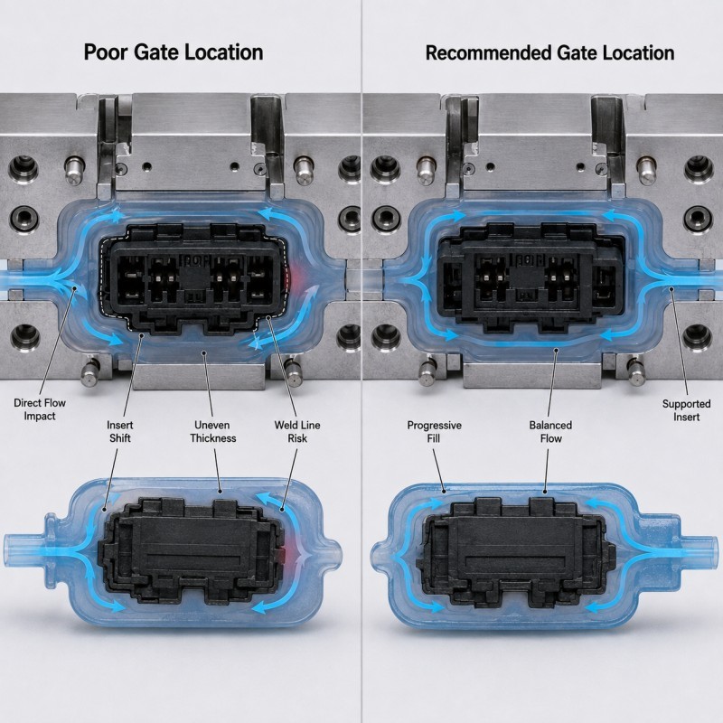
A poor gate location may cause:
• The insert to shift, lift or tilt
• Silicone to split around the insert too early
• Flow fronts to meet on a sealing surface
• Air to become trapped behind the insert
• Thin sealing lips to fill too late
• Local cavity pressure to rise near a shut-off
• Flash around protected openings
• Uneven silicone thickness
• Visible gate marks on cosmetic surfaces
• Different filling behavior between mold cavities
The gate should therefore not be selected only according to where it is easiest to machine the mold.
The better question is:
Where can silicone enter the cavity, establish a stable flow front and progressively fill the functional geometry without creating another quality problem?
The answer depends on the insert structure and the final product function.
What Happens When the Gate Is Too Close to the Insert?
Placing the gate very close to an insert is not automatically wrong, but the initial flow direction must be evaluated carefully.
If the incoming silicone directly strikes a thin plastic wall, FPC edge, cable or unsupported insert, injection flow can create local loading before pressure becomes balanced around the cavity.
Possible results include:
• Insert displacement
• FPC lifting or bowing
• Uneven silicone coverage
• Local flash
• Changed shut-off contact
• Thin silicone on one side
• Excess silicone on the opposite side
The risk is higher when the insert is flexible, thin or supported far away from the gate.
For FPC overmolding, the gate should not direct the first flow front toward exposed contact pads or an unsupported flexible-circuit edge.
For cable overmolding, the incoming flow should not push the cable away from its locating groove.
For plastic housings, the gate should not unnecessarily load a weak wall or sensitive shut-off surface.
The preferred gate region is usually one where the insert has stable support and the silicone can enter the required coverage area without immediately disturbing the protected structure.
Where Should the Gate Be Placed?
There is no universal gate position for every LSR overmolding project.
However, a suitable gate location should normally satisfy several conditions.
1. Start from a Stable Region
The initial flow should enter near a structurally supported area rather than directly loading a flexible insert.
2. Fill Critical Features Predictably
Thin sealing lips, bonding boundaries and mechanical-locking features should receive silicone through a controlled flow path.
3. Keep the Gate Away from Critical Functional Surfaces
Where possible, avoid placing the gate mark on:
• Primary sealing lips
• Contact pads
• Connector mating surfaces
• Precision assembly datums
• Visible Class-A cosmetic surfaces
• Flexible hinge areas
• High-stress bending zones
4. Control Where Flow Fronts Meet
If silicone must divide around an insert, the meeting point should preferably be moved away from the primary sealing surface, high-stress region or critical cosmetic area.
5. Keep the Flow Length Reasonable
A gate should not force silicone to travel unnecessarily through a long thin section before reaching a large cavity region.
6. Design the Final Fill Location
The gate should be considered together with the location where the cavity finishes filling, because that is where remaining air must escape.
Gate location should therefore be selected from the complete flow path rather than from the injection point alone.
Why Must the Gate and Vent Be Designed Together?
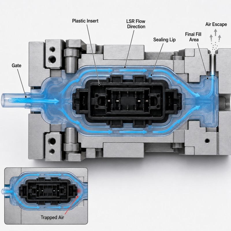
The gate determines where silicone enters the cavity. The vent must allow the displaced air to escape from the final-fill region.
These two features should therefore be designed as one flow system.
Imagine silicone entering from one side of a plastic housing.
If the flow progresses around the insert and finishes at the opposite edge, the vent should be positioned where the remaining air naturally collects.
A poor combination may create a closed pocket behind the insert.
Possible defects include:
• Bubbles
• Internal voids
• Short shots
• Incomplete sealing lips
• Weak bonding areas
• Rough final-fill surfaces
• Local flash caused by pressure buildup
Adding more vents randomly does not correct an unsuitable flow path.
The first question should be where the silicone enters, how it moves around the insert and where the final air pocket is expected to form.
For a detailed review of this issue, see mold venting design for custom LSR overmolding quality.
How Does Gate Location Affect Weld Lines?
When silicone reaches an insert, the original flow front may divide into two or more paths.
These separate flows later meet again.
The meeting region can form a visible or structural weld line.
A weld line is particularly important when it appears on:
• A waterproof sealing lip
• A thin membrane
• A cable bending area
• A mechanical retention boundary
• A bonding edge
• A visible cosmetic surface
Moving the gate changes the route taken by the flow fronts and can therefore change where the meeting line appears.
The objective is not always to eliminate every meeting line.
In many complex insert structures, separated flow fronts are unavoidable.
The practical objective is to move the meeting region toward a lower-risk location and then validate the resulting part through the required functional testing.
For more detail, review why LSR overmolded parts show weld lines, flow marks or weak seams around inserts.
LSR Gate Location DFM Checklist
| DFM Item | What Engineers Should Confirm | Main Risk |
Insert structure | Plastic, metal, FPC or cable geometry is confirmed | Flow moves or deforms insert |
Initial flow direction | Gate does not directly attack a weak insert area | Insert displacement |
Critical surfaces | Seals, contacts and assembly areas are identified | Gate or weld line affects function |
Wall thickness | Thin and thick regions are reviewed | Flow bypasses thin features |
Flow split | Areas where silicone divides around inserts are known | Weld line in critical area |
Final fill area | Last-fill position is predicted | Trapped air |
| Vent location | Air can escape from final-fill region | Bubble or short shot |
| Shut-off | Local pressure does not open protected areas | Flash |
| Multi-cavity balance | Cavities receive repeatable filling | Cavity-to-cavity variation |
The silicone mold design and tooling review should confirm gate location, runner balance, flow direction, insert support, wall thickness, shut-off and venting before mold steel is finalized.
How Should Gate Location Be Validated During Sampling?
Gate location should be validated using actual molded parts rather than only the 3D mold design.
Recommended validation includes:
1. Filling Observation
Check whether thin sealing lips, grooves and mechanical locks fill completely.
2. Insert Position Inspection
Compare the insert location before and after molding to determine whether flow is moving the substrate.
3. Weld-Line Inspection
Identify where separated flow fronts meet and whether the location affects sealing, bonding, bending or appearance.
4. Cross-Section Inspection
Cut samples through critical flow, bonding and retention areas to check for hidden voids or incomplete filling.
5. Flash Inspection
Confirm that local pressure near the gate does not open a shut-off or protected functional area.
6. Multi-Cavity Comparison
Compare gate marks, filling pattern, insert position and final-fill defects between cavities.
7. Functional Testing
Complete waterproof, pull, bending, assembly or electrical testing according to the actual application.
How SiliconePlus Supports Gate and Flow DFM
SiliconePlus supports custom LSR overmolding projects from drawing review and insert evaluation through mold design, sampling, inspection and mass production.
Project support can include:
• Gate and flow-path review
• Insert-positioning analysis
• Wall-thickness review
• Mold shut-off design
• Venting and air-trap analysis
• Mechanical-retention review
• Precision mold manufacturing
• LSR injection molding
• Cross-section and dimensional inspection
• Waterproof, assembly and mechanical test support
• Pilot-production validation
FAQ
Can the Gate Be Placed Directly Next to an Insert?
Yes in some designs, but the initial flow direction, insert support and local cavity pressure must be evaluated. A gate located close to an unsupported insert can increase movement risk.
Should the Gate Be Close to the Thinnest Silicone Area?
Not automatically. The complete flow path, pressure requirement, insert geometry and final-fill venting must be considered together.
Can Moving the Gate Eliminate Weld Lines?
Not always. Complex inserts may naturally split the silicone flow. Moving the gate is often used to move the meeting line toward a lower-risk region instead.
Should the Gate Be Placed on a Sealing Surface?
Where possible, the gate mark should be kept away from the primary sealing contact area.
Can Poor Gate Location Cause Flash?
Yes. An unsuitable flow direction or local pressure condition can contribute to insert movement or opening of a weak shut-off, allowing silicone into an unwanted area.
Can Gate Location Be Finalized Only After the Mold Is Built?
It is better to review the gate during DFM. Changing the gate after tooling may require modifications to the runner, cavity or mold insert structure.
Conclusion
Gate location in LSR overmolding should be treated as a functional design decision rather than only a mold-manufacturing detail.
Reliable gate design requires coordinated review of:
• Insert support
• Initial flow direction
• Wall thickness
• Critical sealing areas
• Flow splitting
• Weld-line position
• Final-fill location
• Venting
• Shut-off
• Multi-cavity balance
The best gate location is the one that allows the silicone to fill the complete overmolded structure predictably without moving the insert or placing major flow defects in critical functional areas.