Why Do LSR Overmolded Parts Show Weld Lines, Flow Marks, or Weak Seams Around Inserts?
Introduction
An LSR overmolded component may appear fully filled but still show a visible line, cloudy band, gloss difference, color variation, or weak seam around an insert.
The line often appears where two separate silicone flow fronts travel around a plastic housing, metal terminal, FPC, connector, cable, or electronic insert and then meet again on the opposite side.
In some products, the line is only a cosmetic difference. In other products, the same location may become:
- A weak bending area
- A tear-initiation point
- A visible surface defect
- A bonding weakness
- An air-trap location
- A waterproof leakage path
- A dimensional inconsistency
- A source of cavity-to-cavity variation
This problem is commonly described using several different terms:
- Weld line
- Knit line
- Flow line
- Flow mark
- Meeting line
- Weak seam
- Flow-front boundary
These terms are sometimes used interchangeably, but they do not always describe exactly the same defect.
For engineers, quality teams, sourcing managers, and OEM buyers, the important question is not only:
“Can we see a line on the silicone?”
The more important question is:
“Does the line affect appearance, bonding, bending strength, sealing performance, assembly, or long-term reliability?”
This guide explains why weld lines and flow marks appear in precision liquid silicone injection molding and how they should be evaluated before tooling and mass production.
Answer Excerpt
LSR weld lines form when two or more liquid silicone flow fronts travel through different paths inside the mold and meet again before curing is complete.
This commonly happens when silicone flows around plastic, metal, FPC, cable, connector, or electronic inserts. The insert divides the original flow front, and the separated material must reconnect behind it.
The final seam quality depends on gate position, flow-path length, mold temperature, silicone temperature, injection speed, cavity pressure, wall thickness, insert geometry, venting, contamination, material condition, and the time at which the flow fronts meet.
A visible line is not automatically a product failure. However, seams located on sealing lips, bonding boundaries, flexible hinges, cable exits, thin membranes, cosmetic surfaces, or high-stress areas should be validated through visual inspection, dimensional measurement, bending, pull, leak, aging, and pilot-production testing.
1. What Is an LSR Weld Line?
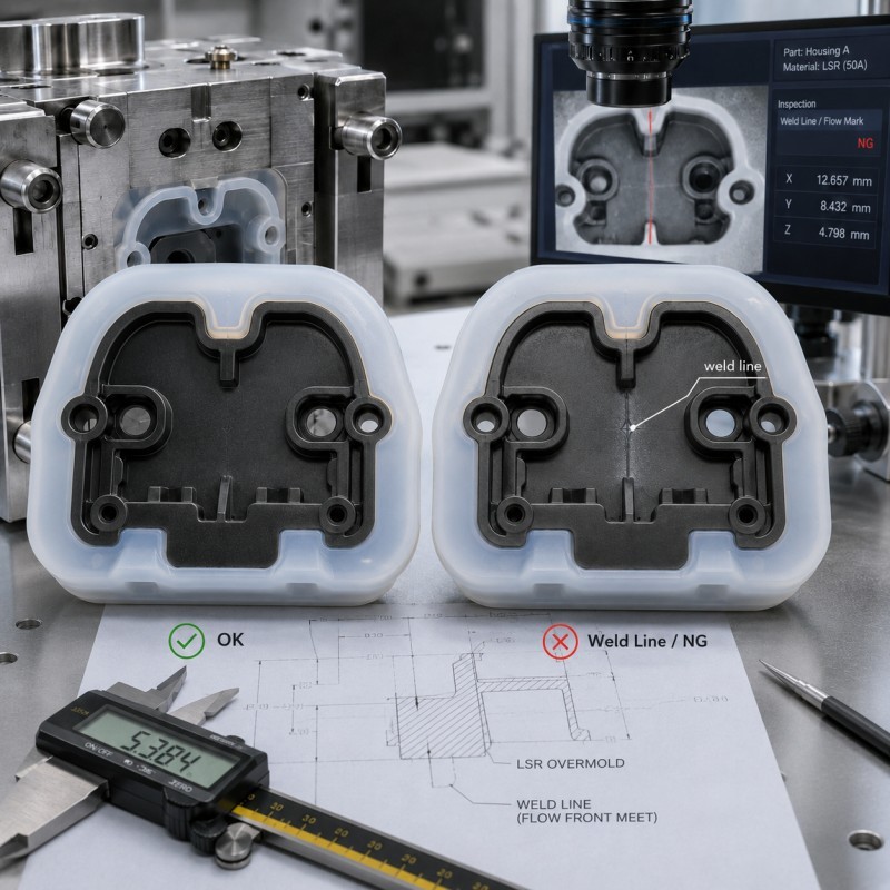
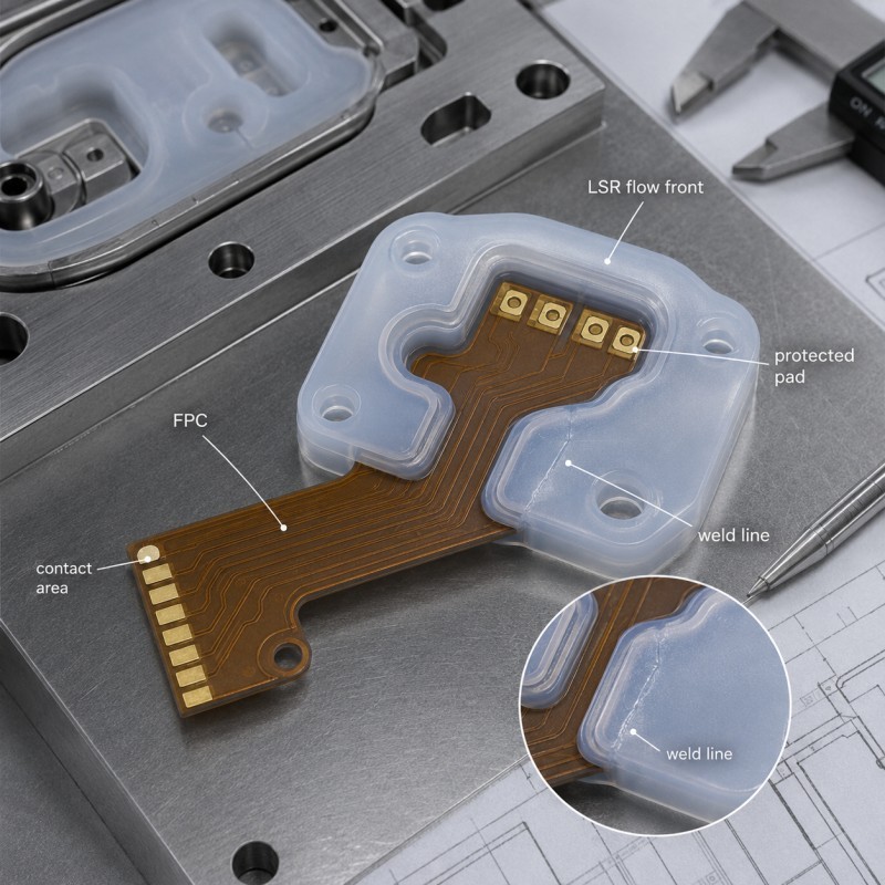
An LSR weld line is the boundary formed when two separate silicone flow fronts meet inside the mold.
The flow may separate because of:
- A plastic insert
- A metal terminal
- An FPC stiffener
- A hole or core pin
- A cable
- A sensor housing
- A mechanical-locking feature
- A cavity rib
- Multiple injection gates
- A complex product shape
Imagine liquid silicone entering one side of a cavity and encountering a plastic insert.
Part of the material flows around the left side of the insert. Another part flows around the right side. The two streams meet again behind the insert.
The area where they reconnect becomes the weld line.
When the flow fronts meet under suitable temperature, pressure, cleanliness, and timing conditions, the line may be visually minor and mechanically acceptable.
When they meet too late, contain trapped air, have begun curing, or are separated by contamination, the seam may become more visible or weaker.
2. A Flow Mark Is Not Always the Same as a Weld Line
A flow mark may describe a visual surface change caused by how the silicone travels through the cavity.
It may appear as:
- A glossy line
- A matte band
- A cloudy patch
- A color streak
- A wave pattern
- A change in texture
- A visible gate shadow
- A directional surface pattern
A weld line specifically relates to separate flow fronts meeting.
A flow mark may occur even when there is only one main flow front.
Possible flow-mark causes include:
- Injection-speed variation
- Uneven mold temperature
- Sudden wall-thickness change
- Pigment dispersion
- Gate position
- Surface contamination
- Mold texture
- Material beginning to cure
- Pressure variation
Failure analysis should first determine whether the defect is:
- A true meeting line
- A general flow pattern
- A pigment streak
- A curing difference
- A surface-texture variation
- An internal air trap
- A bonding boundary
Changing the gate will not necessarily solve a defect caused by pigment dispersion or mold-surface damage.
3. Inserts Divide the Silicone Flow Front
Insert overmolding creates additional flow complexity compared with molding a separate silicone component.
The insert may block the direct path between the gate and the final filling area.
The silicone must then:
- Reach the insert
- Separate into several flow paths
- Travel around the insert
- Fill narrow areas
- Expel trapped air
- Reconnect behind the insert
- Complete curing without leaving a weak seam
The insert may be:
- Plastic
- Metal
- FPC
- Cable
- Connector
- Sensor housing
- Electronic module
- Pre-molded silicone
- Glass or ceramic
The larger and more complex the insert is, the more strongly it can influence material flow.
Small changes in insert position may also change which flow front reaches the meeting area first.
This is why stable insert positioning affects not only silicone thickness and exposed areas but also flow balance and weld-line position.
4. Gate Position Determines Where the Flow Fronts Meet
The gate is the location where LSR enters the mold cavity.
Its position influences:
- Flow direction
- Flow distance
- Cavity pressure
- Insert coverage
- Weld-line position
- Air-trap location
- Surface appearance
- Filling balance
- Final dimensional behavior
If the gate is placed directly opposite a critical insert feature, silicone may divide around the insert and reconnect on a visible or highly stressed surface.
A gate may therefore create a weld line on:
- A sealing lip
- A bending zone
- A cosmetic surface
- A button dome
- A cable exit
- A bonding edge
- A thin membrane
- A waterproof contact area
Gate design should aim to move the meeting line toward a lower-risk area whenever the product structure permits.
However, relocating the gate may also affect:
- Fill pressure
- Venting
- Cold-runner structure
- Cycle time
- Flash
- Material waste
- Demolding
- Multiple-cavity balance
Gate location should therefore be reviewed as part of the complete mold-flow strategy rather than changed independently.
Gate position, meeting-line location and critical functional surfaces should be reviewed during the DFM process before final tooling.
Official LSR processing guidance recommends balancing the runner system so cavities fill evenly and using filling studies or simulation during mold development.
5. Multiple Gates Can Create Additional Meeting Lines
Some larger or more complex products require more than one injection point.
Multiple gates may help:
- Reduce flow distance
- Fill thin sections
- Balance a large cavity
- Reduce pressure loss
- Improve cycle stability
However, every additional gate can create another location where separate flow fronts meet.
If two gates do not fill at the same rate, one flow front may reach the meeting area earlier and begin curing before the second front arrives.
Possible results include:
- Visible seam
- Uneven gloss
- Local hardness difference
- Weak bonding between flow fronts
- Internal air trap
- Asymmetric filling
- Different appearance between cavities
For multi-gate designs, engineers should review:
- Gate size
- Gate timing
- Runner balance
- Flow distance
- Mold temperature
- Needle-valve control
- Final meeting location
- Cavity pressure
- Vent position
A second gate should not be added only to compensate for an unresolved venting or wall-thickness problem.
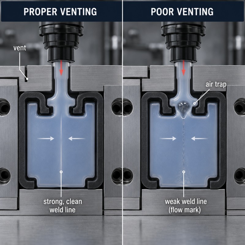
6. Poor Venting Traps Air at the Meeting Point
Air inside the cavity must escape as silicone fills the mold.
A controlled mold venting design is especially important near the final filling and weld-line areas.
The last-filling area is often the same area where separate flow fronts meet.
If air cannot escape, it may remain between the approaching silicone fronts and create:
- White edges
- Bubbles
- Voids
- Incomplete filling
- Weak seams
- Surface burning or discoloration
- Poor texture transfer
- Local bonding instability
- Reduced sealing reliability
Dow’s LSR processing guide states that venting should be placed in the area reached last by the material. It also notes that incomplete air removal can create visible white edges and reduce mechanical strength along the weld line.
Venting should be designed according to:
- Final filling position
- Insert geometry
- Gate location
- Flow-path length
- Silicone viscosity
- Mold shutoff
- Flash requirement
- Sealing-surface location
- Vacuum capability
Increasing the vent depth without analysis may reduce trapped air but create unacceptable flash.
The objective is controlled air release, not simply the largest possible vent.
7. The Flow Front May Begin Curing Before It Reconnects
LSR is injected into a heated mold and begins curing as it travels through the cavity.
A flow front that travels a longer path may have a different cure history from one traveling a shorter path.
The risk increases when:
- The flow path is long
- The silicone layer is very thin
- Mold temperature is high
- Injection speed is too slow
- The gate is too small
- The insert absorbs or redirects heat
- Flow pauses around a complex structure
- The two fronts arrive at different times
If one flow front has already begun curing significantly before the other arrives, the two fronts may not merge as uniformly.
The seam may then show:
- Visible boundary
- Poor surface texture
- Reduced elasticity
- Weak tear resistance
- Local cracking after bending
- Inconsistent appearance after aging
The solution is not automatically lowering the complete mold temperature.
Changing temperature can affect curing time, bonding, cycle time, flash, demolding, and insert stability.
Gate, speed, pressure, wall thickness, and flow distance should be reviewed together.
8. Injection Speed Influences Flow-Front Temperature and Timing
Injection speed affects how quickly the silicone fills the cavity.
If the speed is too low:
- Flow fronts may cool or cure differently
- Filling time increases
- Meeting fronts may arrive at different stages
- Thin areas may stop filling
- Surface marks may become more visible
If the speed is too high:
- Air may be compressed
- Insert movement may increase
- Flash risk may rise
- Flow turbulence may become less stable
- Sensitive FPC or terminals may shift
- Excessive local pressure may occur
The correct speed should produce:
- Complete cavity filling
- Stable insert positioning
- Controlled cavity pressure
- Reliable air release
- Consistent meeting-front timing
- Acceptable flash
- Repeatable appearance
The machine settings should be established through controlled mold trials rather than adjusted only according to whether the cavity appears full.
9. Injection Pressure Cannot Correct Every Weld-Line Problem
Increasing injection pressure may temporarily make a seam look less obvious because the flow fronts are forced together more strongly.
However, excessive pressure can create other defects:
- Flash
- Insert movement
- Plastic deformation
- Blocked holes
- Uneven silicone thickness
- Mold-shutoff leakage
- FPC displacement
- Higher residual stress
- Cavity imbalance
A weak seam caused by trapped air cannot be solved reliably by pressure alone.
A weld line caused by early curing may require changes to flow distance, gate location, injection timing, or mold temperature.
Pressure should be adjusted inside a stable process window after the mold-flow and venting structure have been reviewed.
10. Wall Thickness Controls How Easily the Fronts Reconnect
Silicone flows more easily through some sections than others.
A sudden change from a thick area to a thin area can divide or delay the flow.
Thin sections may:
- Fill later
- Lose pressure
- Begin curing earlier
- Trap air
- Produce visible meeting lines
- Become sensitive to small process changes
Thick sections may:
- Fill first
- Retain more heat
- Redirect the flow front
- Create uneven cavity pressure
- Cause another area to become the final filling point
Common high-risk structures include:
- Thin sealing lips behind thick inserts
- Narrow bridges between two larger silicone areas
- Thin membranes around metal terminals
- FPC coverage beside a thick connector
- Small cable-exit transitions
- Thin cosmetic skins over rigid plastic
- Narrow mechanical-locking passages
Gradual thickness transitions can help create more predictable material flow.
A wall-thickness problem should be reviewed before increasing pressure or adding another gate.
11. Sharp Insert Corners Change the Flow Direction
Silicone must turn around the edges of the insert.
Sharp corners can cause:
- Sudden flow separation
- Local pressure loss
- Air entrapment
- Flow hesitation
- Thin silicone coverage
- Stress concentration
- Visible seams behind the corner
A rounded insert edge can often provide a smoother flow path than a sharp 90-degree corner.
However, edge radius also affects:
- Product dimensions
- Bonding area
- Silicone thickness
- Mechanical retention
- Assembly clearance
- Insert manufacturing cost
During DFM, engineers should review the hidden insert geometry under the silicone, not only the external appearance of the finished component.
A smooth external silicone surface may still contain a difficult flow path created by the substrate underneath.
12. Holes and Mechanical Locks Can Create Small Weld Lines
Mechanical retention structures often use:
- Through-holes
- Slots
- Grooves
- Undercuts
- Perforations
- Cross-holes
- Wraparound features
Silicone flows into or through these features and may reconnect on the opposite side.
This can improve physical retention, but it may also create small weld-line areas.
Risks include:
- Air trapped inside holes
- Incomplete filling
- Weak silicone bridges
- Visible lines
- Local tearing
- Unstable mechanical locking
- Flash around the feature
- Difficult inspection
Mechanical locking should therefore be designed together with:
- Gate location
- Venting
- Hole size
- Hole edge radius
- Silicone thickness
- Flow direction
- Insert strength
- Required pull resistance
A locking hole that is too small may be difficult to fill reliably.
A very large locking feature may weaken the plastic or metal insert.
13. Surface Contamination Can Prevent the Flow Fronts From Joining Cleanly
Material or surface contamination can collect at the front of the flowing silicone.
Possible contamination sources include:
- Excess mold-release agent
- Machine oil
- Insert-cleaning residue
- Dust
- Fibers
- Plastic particles
- Metal-stamping oil
- Primer buildup
- Previous material
- Contaminated gloves
- Mold deposits
When separate flow fronts push contamination toward the same meeting location, the material between them may prevent uniform joining.
WACKER’s processing guide notes that mold-release agent pushed ahead by the material flow can lead to undesirable weld lines because the merging flow fronts do not weld completely.
For overmolding projects, contamination can also affect the silicone-to-substrate bonding interface.
Cleaning, handling, primer, mold maintenance, and insert storage should therefore be controlled before molding.
14. Insert Positioning Changes the Weld-Line Location
A small insert shift changes the space available for silicone flow.
Stable insert positioning helps maintain consistent silicone thickness, flow balance and meeting-line location.
One side of the insert may have a wider flow path while the opposite side becomes narrower.
This can cause:
- One flow front arriving earlier
- A different final meeting point
- Uneven silicone thickness
- Asymmetric appearance
- Air being trapped in a new location
- The seam crossing a sealing surface
- Cavity-to-cavity variation
Insert movement may include:
- Horizontal shift
- Vertical shift
- Rotation
- Tilting
- FPC bowing
- Cable movement
- Terminal movement
- Plastic warpage
Stable positioning fixtures should be designed to control both insert location and silicone flow space.
A mold-flow analysis based on a perfectly centered CAD insert may not represent production when real inserts shift inside the fixture.
15. Plastic, Metal, and FPC Inserts Create Different Flow Conditions
Plastic Inserts
Silicone over plastic projects require the mold to balance material flow around ribs, holes, thin walls and complex housing structures.
Plastic inserts may have:
- Ribs
- Bosses
- Thin walls
- Holes
- Curved housings
- Warpage
- Variable shrinkage
Plastic deformation can change the silicone flow path during molding.
A thin plastic wall may also move under pressure, causing the weld line to shift or become inconsistent.
Metal Inserts
Silicone over metal projects may involve terminals, pins, holes, stamped edges and high-conductivity inserts that influence local flow and temperature.
Metal inserts may have:
- Sharp stamped edges
- Terminals
- Threads
- Small holes
- Plating
- Burrs
- High thermal conductivity
Metal can change the local temperature around the flow front and may create narrow flow passages near terminals or edges.
FPC Inserts
FPC silicone overmolding is more difficult to balance because the circuit is thin, flexible and easy to move.
It may bow, stretch, move, or create different flow spaces above and below the circuit.
The mold must protect exposed pads and components while maintaining balanced flow around the FPC structure.
For FPC overmolding, the seam location should not interfere with:
- Contact pads
- Bending zones
- Solder joints
- Sensor areas
- Waterproof boundaries
- Cable exits
Each substrate type requires a different mold-flow and fixture strategy.
16. Weld Lines Can Be More Visible on Certain Colors and Textures
A seam may be easier to see on:
- Black silicone
- Dark blue silicone
- Dark gray silicone
- Transparent silicone
- Translucent silicone
- High-gloss surfaces
- Fine matte textures
- Cosmetic Class-A surfaces
Dark colors create strong contrast when the surface reflects light differently.
Transparent silicone can reveal:
- Internal air
- Flow-front boundaries
- Micro-voids
- Material variation
- Insert shadows
A matte surface may hide some gloss differences but make a raised or uneven seam more visible under directional lighting.
Appearance standards should define:
- Lighting
- Viewing distance
- Viewing angle
- Product orientation
- Background
- Acceptable line length
- Acceptable line width
- Critical cosmetic areas
A photograph taken under strong magnification should not be the only acceptance method unless that inspection condition has been agreed in advance.
17. A Visible Weld Line Is Not Automatically a Weak Seam
Some weld lines are mainly cosmetic.
The line may be visible because of:
- Light reflection
- Texture direction
- Pigment orientation
- Surface gloss
- Local flow history
The material may still be mechanically continuous and suitable for the application.
However, greater attention is required when the seam:
- Opens during bending
- Turns white under strain
- Tears during pull testing
- Contains bubbles
- Shows incomplete filling
- Crosses a sealing lip
- Is located at a bonding edge
- Grows after thermal cycling
- Allows water or air leakage
- Changes between production cavities
The acceptance decision should be based on product function.
A minor line on a hidden, low-stress surface may be acceptable.
The same line on a waterproof membrane, flexible button, cable strain relief, or medical-device contact surface may require stricter validation.
18. Weld Lines Can Affect Waterproof Performance
A weld line crossing a sealing path may become a leakage risk when it contains:
- Trapped air
- Incomplete material joining
- Surface depression
- Local hardness variation
- Small tear
- Uneven compression
- Bonding separation
The component may pass visual inspection but fail:
- Air-leak testing
- Pressure-decay testing
- Water immersion
- Thermal cycling
- Repeated bending
- Vibration
- Long-term compression
Waterproof validation should inspect the actual weld-line location.
The test plan may include:
- Initial visual inspection
- Dimensional measurement
- Initial leak testing
- Environmental cycling
- Bending or vibration
- Repeat leak testing
- Microscopic or cross-section inspection
A material flow seam should not be placed on a critical sealing lip when the design provides a practical alternative.
19. Weld Lines Can Affect Bending and Tear Resistance
A seam located in a repeatedly flexed area may experience concentrated strain.
High-risk areas include:
- Cable exits
- FPC transitions
- Flexible hinges
- Button roots
- Thin sealing membranes
- Wearable straps
- Soft-touch handles
- Connector covers
- Strain-relief sections
During bending, the seam may show:
- Whitening
- Surface opening
- Small cracks
- Reduced recovery
- Local tearing
- Delamination near the insert
The required test should reproduce the real bending direction.
A seam that is stable under straight tension may behave differently under repeated bending, twisting, or peel loading.
20. Why Can a Sample Look Good but Mass Production Show More Weld Lines?
Engineering samples are commonly produced under close supervision.
During sampling:
- Inserts may be selected carefully
- Mold surfaces are clean
- Injection parameters are adjusted slowly
- Production runs are short
- Every sample is inspected
- One cavity may receive more attention
Mass production introduces:
- Longer continuous runs
- Mold-temperature drift
- Multiple cavities
- Material-batch changes
- Insert-batch variation
- Operator changes
- Fixture wear
- Vent contamination
- Mold deposits
- Faster loading cycles
- Tool wear
A process with limited flow margin may produce an acceptable short trial but become unstable during a long run.
Pilot production should evaluate:
- Every mold cavity
- Beginning and end of the run
- Different insert batches
- Different material batches
- Seam location
- Seam visibility
- Mechanical performance
- Waterproof performance
- Vent-cleaning intervals
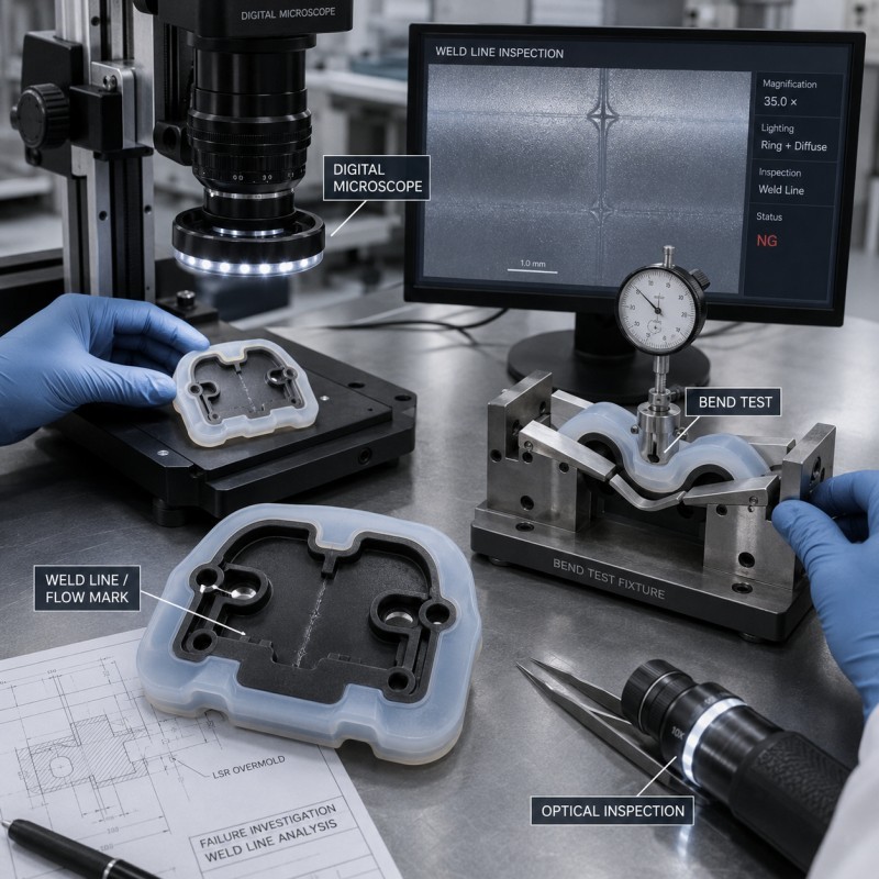
21. How Should an LSR Weld-Line Problem Be Investigated?
Use a controlled investigation rather than changing several molding variables together.
Recommended sequence:
- Identify whether the defect is a weld line, flow mark, pigment streak, air trap, or surface-texture difference.
- Mark the exact defect location on the drawing.
- Identify which mold cavity produced the part.
- Compare passing and failing samples.
- Review the gate and expected flow path.
- Check whether the defect is located at the last-filling area.
- Inspect the vent for contamination or damage.
- Measure insert position and silicone flow space.
- Compare different insert batches.
- Review injection speed, volume, and pressure.
- Review mold temperature and cycle time.
- Inspect for mold-release or surface contamination.
- Check wall thickness and sudden transitions.
- Perform bending, pull, leak, or assembly testing as required.
- Inspect the seam under magnification.
- Use cross-section analysis when the internal condition is unclear.
- Change one controlled variable and repeat the test.
Do not change gate size, vent depth, mold temperature, injection speed, and insert fixture simultaneously.
Changing one variable at a time makes the root cause easier to identify.
22. What Should Be Validated Before Mass Production?
Before approving an LSR overmolded component, buyers and manufacturers should confirm:
- Final silicone material
- Silicone hardness
- Substrate material
- Insert dimensions
- Insert-positioning method
- Gate location
- Number of gates
- Runner balance
- Expected flow direction
- Final meeting-line location
- Wall thickness
- Insert-edge geometry
- Mechanical-locking structure
- Venting location
- Mold temperature
- Injection-process window
- Surface-cleaning requirements
- Primer or treatment process
- Appearance standard
- Critical cosmetic areas
- Critical sealing areas
- Bending requirement
- Pull or tear requirement
- Waterproof-test method
- Environmental tests
- Cavity-to-cavity consistency
- Pilot-production quantity
- Mold-maintenance plan
- Reference samples
- Traceability records
The drawing should distinguish between:
- Areas where a minor visual line may be acceptable
- Areas requiring controlled appearance
- Functional areas where weak seams are not acceptable
How SiliconePlus Supports Weld-Line and Flow-Control Projects
SiliconePlus provides custom liquid silicone injection molding and silicone overmolding services for precision components used in automotive electronics, 3C electronics, sensors, medical devices, wearable products, beauty devices, and industrial equipment.
Our capabilities include:
- DFM and drawing review
- Gate and flow-path evaluation
- Mold-flow and final-fill review
- Mold-venting design
- Liquid silicone injection molding
- Silicone over plastic
- Silicone over metal
- FPC silicone overmolding
- Precision insert positioning
- Mechanical-locking review
- Custom mold development
- Process-parameter optimization
- Surface and appearance inspection
- Dimensional inspection
- Bending and assembly evaluation
- Waterproof-test coordination
- Sample and pilot production
- OEM/ODM mass production
With 25+ years of silicone manufacturing experience, our team helps customers review the complete relationship between the insert, silicone structure, gate, flow path, venting, meeting-line position, appearance standard, and functional requirement.
The objective is not only to hide a visible line.
The objective is to establish a stable process in which separate flow fronts reconnect consistently without affecting sealing, bonding, bending, assembly, or long-term reliability.
What Information Should Buyers Send for Evaluation?
To evaluate an LSR weld-line or flow-mark problem, buyers should provide:
- 2D drawing
- 3D file
- Product or sample photos
- Defect close-up photos
- Substrate material
- Insert drawing
- Silicone material
- Silicone hardness
- Silicone coverage area
- Critical cosmetic areas
- Critical sealing areas
- Required bending direction
- Gate information, when available
- Mold-cavity number
- Known defect location
- Waterproof requirements
- Mechanical test requirements
- Current production quantity
- Estimated future quantity
- Sample and production records
When a project has already failed, provide passing and failing samples from different mold cavities and production periods whenever possible.
Frequently Asked Questions
What is the difference between a weld line and a flow mark?
A weld line forms where separate silicone flow fronts meet. A flow mark is a broader visual defect related to material movement, temperature, pressure, pigment, wall thickness, gate position, or mold texture.
Does every LSR part with an insert have a weld line?
Not necessarily a visible or harmful one. An insert often divides the flow, but suitable gate placement, balanced filling, venting, temperature, and geometry can make the meeting area stable and visually minor.
Can higher injection pressure eliminate a weld line?
Not always. Higher pressure may reduce some visible effects but can also cause flash, insert movement, deformation, or blocked openings. Trapped air, early curing, contamination, and poor gate location require different solutions.
Can a weld line cause water leakage?
Yes, when the seam contains trapped air, incomplete joining, surface depression, local tearing, or inconsistent compression and crosses a critical waterproof path.
Why is the weld line located behind the insert?
The insert separates the silicone into different flow paths. The material streams travel around it and meet again on the opposite side.
Can the gate be moved after the mold is completed?
Some gate changes may be possible, but major relocation can require significant cold-runner or mold modification. Gate and flow direction should be reviewed before final tooling.
Can mold-flow simulation predict the exact weld line?
Simulation can help predict flow paths, meeting areas, pressure, and air-trap risks, but actual material, insert tolerance, surface condition, mold temperature, venting, and production parameters must still be validated through mold trials.
Is a visible seam acceptable on a cosmetic product?
Acceptance depends on the agreed surface standard, color, texture, viewing conditions, product position, and whether the seam affects mechanical or functional performance.
What testing is needed for a weld line?
Depending on the product, testing may include visual inspection, dimensional measurement, bending, tensile or pull testing, tear evaluation, leak testing, thermal cycling, vibration, assembly testing, and microscopic inspection.
Conclusion
Weld lines, flow marks, and weak seams in LSR overmolding are not caused by one universal molding parameter.
They may result from insert geometry, gate position, multiple flow paths, poor venting, trapped air, early curing, wall-thickness changes, injection speed, pressure, contamination, insert movement, mold-temperature variation, or continuous-production conditions.
A visible line is not automatically a product failure, but seams located on sealing, bonding, bending, cosmetic, or high-stress areas require controlled validation.
The most reliable approach is to review the expected flow path before tooling, position the gate and vent according to the final filling area, stabilize the insert, control the process window, and validate the seam during pilot production.
If you are developing an LSR overmolded connector, FPC component, sensor, cable assembly, metal insert, plastic housing, or waterproof electronic part with visible flow marks or weak meeting lines, contact SiliconePlus and send us your drawings, substrate material, defect photos, silicone requirement, functional areas, testing standards, and estimated quantity. Our engineering team will review the project and provide practical manufacturing recommendations.