Why Do LSR Overmolded Electronic Housing Gaskets Leak at Corners?
Answer Excerpt
Corner leakage in an LSR overmolded electronic housing gasket is usually caused by uneven sealing compression rather than by the corner shape alone. The risk increases when the silicone path changes direction abruptly, the plastic housing warps, the mating cover does not remain flat, the local gasket height changes, or a parting line or mold mismatch crosses the corner sealing surface. Reliable corner sealing requires the silicone path, groove, plastic support, compression and final housing assembly to be reviewed as one system.
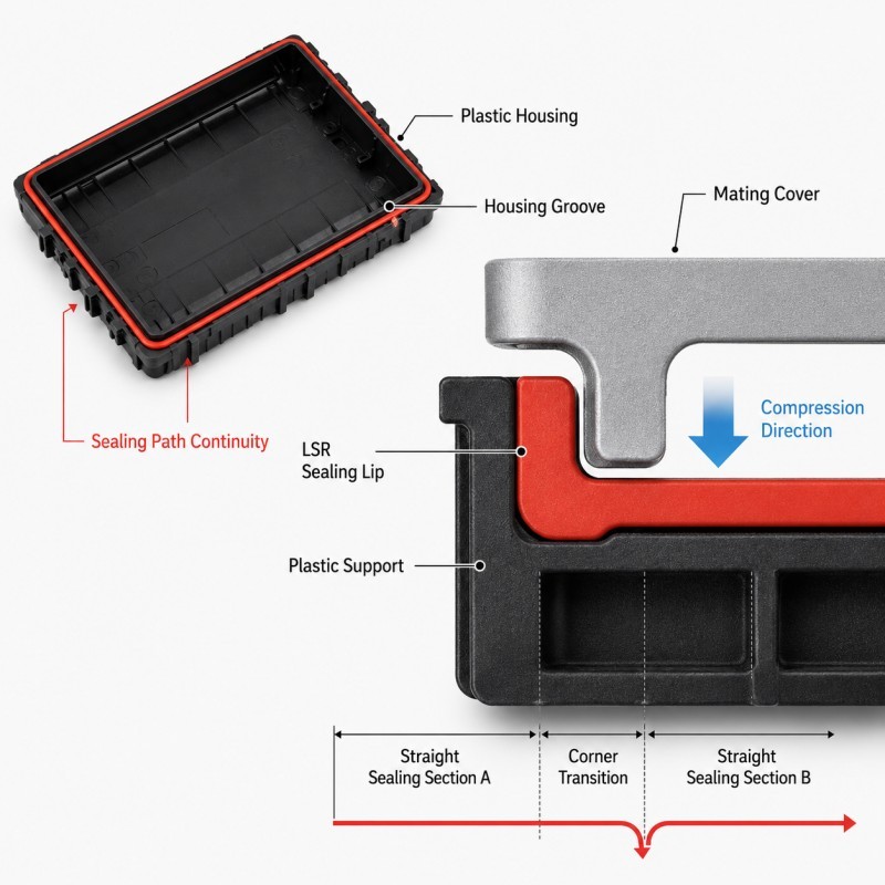
Electronic housing seals often follow a rectangular or irregular perimeter around the product enclosure.
Straight sections are relatively easy to understand because the compression direction and sealing width remain consistent.
At a corner, however, the sealing path changes direction while several tolerances meet in the same small area.
The silicone may also be surrounded by a different amount of plastic support than it has along a straight wall.
This is why a housing gasket can pass visual inspection and still develop leakage first at a corner during air-leak, pressure-decay or waterproof testing.
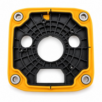
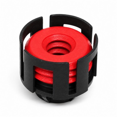
For an actual integrated silicone-over-plastic enclosure structure, review our LSR overmolded electronic housing waterproof silicone gasket.
Why Are Corners More Sensitive to Leakage?
A corner combines several geometric and assembly variables in a small area.
Possible differences between a straight sealing section and a corner include:
• Different local silicone support
• Changing sealing direction
• Different groove geometry
• Housing corner warpage
• Mating-cover flatness variation
• Local gasket-height variation
• Parting-line or flash location
• Different assembly stiffness
• Greater sensitivity to dimensional stack-up
The corner itself is not automatically a defect.
A well-designed corner can seal reliably.
The problem appears when the sealing contact becomes less uniform at the direction change.
For example, the straight sides of a rectangular housing may receive stable compression while a corner becomes slightly lifted because the plastic housing or cover is warped.
The opposite condition can also occur: the corner may receive excessive local compression while nearby straight sections receive less compression.
The design target is therefore not simply to make the silicone thicker at the corner.
The target is to maintain a continuous sealing path with predictable compression through the complete direction change.
What Happens When the Corner Transition Is Too Abrupt?
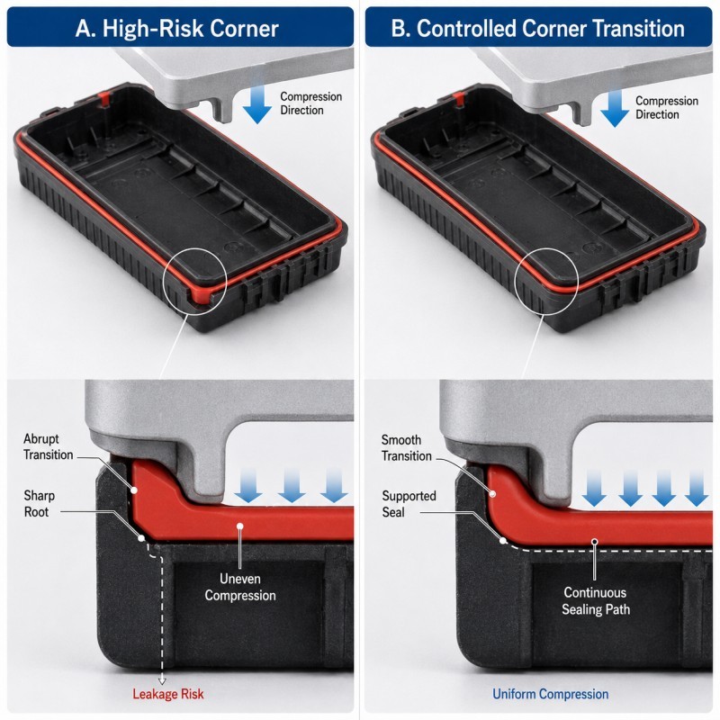
A very abrupt sealing-path transition can make the corner more sensitive to molding and assembly variation.
Possible risks include:
• Local silicone thickness change
• Uneven material flow around the corner
• Air trapping near the final-fill region
• A sharp stress concentration at the gasket root
• Difficult demolding
• Local compression variation
• Flash or mismatch becoming more critical
• Reduced support from the plastic housing
This does not mean that every 90-degree housing corner must be replaced by one universal radius.
The correct geometry depends on the available product space, housing design, silicone hardness, sealing width, mold structure and mating cover.
However, the silicone path should not contain an unnecessary sharp internal notch or sudden thickness change at the same location where the seal also has to bend around the housing corner.
Where product geometry allows, a smoother and better-supported corner transition can make the sealing behavior more predictable.
How Should the Corner Transition Be Designed?
A reliable corner transition should keep the sealing path continuous while maintaining enough silicone support through the direction change.
Engineers should review:
• Corner radius
• Sealing-lip width
• Silicone height
• Groove width
• Root radius
• Local wall thickness
• Plastic support below the silicone
• Mating-cover geometry
• Compression direction
• Parting-line position
The corner should transition into the straight sealing sections without an unnecessary sudden change in silicone thickness.
The plastic housing beneath the LSR should also remain sufficiently rigid so that the sealing lip is not pushed away from the mating cover during assembly.
If the sealing lip becomes wider or thicker only at the corner, that change should have a functional reason and should be checked through compression analysis.
The design should also keep mold parting-line flash or mismatch away from the most critical corner contact area whenever the tool structure permits it.
For a detailed review of this issue, see where the mold parting line should be placed on LSR overmolded seals.
Why Does Corner Compression Become Uneven?
A gasket corner can have the correct molded dimensions and still be compressed incorrectly after assembly.
The final compression depends on the complete enclosure.
Important variables include:
• Upper-cover flatness
• Lower-housing flatness
• Screw or snap position
• Housing stiffness
• Sealing-lip height
• Groove depth
• Compression-stop height
• Corner warpage
• Assembly sequence
• Local plastic thickness
A fastener located close to one corner may create more local closing force than another corner.
A large plastic cover may also bow between screw positions.
This can produce a housing that appears fully assembled while the actual silicone compression differs around the perimeter.
The design should therefore evaluate the complete sealing path rather than measuring one gasket cross-section and assuming that the same compression exists everywhere.
For rectangular electronic housings, the four corners should be included in the assembly validation plan because they can respond differently from the long straight sections.
How Does Tolerance Stack-Up Affect Corner Sealing?
Corner sealing should not be evaluated only at nominal CAD dimensions.
The final local compression may be affected by:
• Silicone sealing-lip height
• Groove depth
• Plastic housing thickness
• Cover flatness
• Housing warpage
• Corner radius variation
• Assembly-stop height
• Mold-cavity variation
• Parting-line mismatch
• Final assembly position
At minimum, engineers should consider three conditions.
Minimum Compression Condition
The housing and gasket tolerance combination creates the largest local gap.
The corner must still maintain continuous sealing contact.
Nominal Compression Condition
The housing, gasket and cover are near their nominal dimensions.
This condition is useful for initial design review but should not be the only approval condition.
Maximum Compression Condition
The local assembly gap becomes smallest and the silicone receives the greatest deformation.
The corner should not roll, pinch, tear or become excessively squeezed out of the sealing path.
Where rigid housing features control the final closing position, review how compression stops should be designed for LSR overmolded seals.
Electronic Housing Gasket Corner DFM Checklist
DFM Item | What Engineers Should Confirm | Main Risk |
Sealing path | Continuous perimeter is clearly defined | Corner leak and assembly tests are defined |
Corner geometry | Transition matches actual housing space | Abrupt deformation |
Lip width | Width remains controlled through the corner | Uneven contact |
Lip height | Corner height matches required compression | Under- or over-compression |
Root transition | Sharp unsupported notch is avoided | Stress or tear risk |
| Plastic support | Housing remains rigid below the corner seal | Seal moves away from cover |
Housing flatness | Upper and lower parts are evaluated | Local sealing gap |
| Parting line | Kept away from critical corner contact where possible | Flash changes compression |
| Assembly stop | Final housing gap is controlled | Compression depends on force |
| Fastener position | Corner closing force is considered | Uneven perimeter compression |
Validation | Corner leak and assembly tests are defined | Straight sections pass but corners fail |
The silicone mold design and tooling review should confirm the gasket path, corner transition, local plastic support, parting-line position, gate, venting and demolding direction before mold steel is finalized.
How Should Housing Gasket Corners Be Validated?
Corner sealing should be validated on the final assembled housing rather than only on the loose overmolded plastic component.
Recommended validation includes:
1. Visual Inspection
Inspect all four corners for flash, mismatch, tearing, uneven silicone boundaries and local deformation.
2. Dimensional Inspection
Measure critical sealing-lip height, groove position and corner geometry.
3. Assembly Inspection
Confirm that the upper cover reaches the intended final position without pinching, rolling or displacing the silicone.
4. Corner Contact Review
Where appropriate, use section analysis or another controlled inspection method to understand how the corner seal contacts the mating cover.
5. Leak Testing
Complete the agreed air-leak, pressure-decay, immersion or other waterproof test on the final enclosure.
6. Minimum and Maximum Compression Evaluation
Check representative tolerance conditions rather than only nominal samples.
7. Thermal Cycling
Repeat sealing inspection after defined temperature cycling when required by the product application.
8. Multi-Cavity and Pilot Production
Compare multiple mold cavities and consecutive production cycles before mass-production approval.
If a leak repeatedly appears at the same corner, the corrective action should focus on the local assembly and sealing geometry rather than simply increasing the overall silicone hardness or gasket thickness.
How SiliconePlus Supports Electronic Housing Seal DFM
SiliconePlus supports custom LSR overmolded electronic housing gasket projects from housing and sealing-path review through tooling, sampling, inspection and mass production.
Project support can include:
• Plastic housing and mating-cover review
• Continuous sealing-path analysis
• Corner-transition DFM
• Silicone lip geometry review
• Housing and groove tolerance analysis
• Compression and assembly review
• Parting-line and mold shut-off review
• Gate and venting analysis
• Precision mold development
• LSR injection molding
• Dimensional inspection
• Assembly and waterproof test support
• Pilot-production validation
Specific corner geometry, gasket dimensions, silicone hardness, compression and waterproof acceptance criteria should always be confirmed according to the actual electronic housing, mating cover and agreed test method.
FAQ
Do All 90-Degree Gasket Corners Leak Easily?
No. A 90-degree housing layout can seal reliably when the silicone geometry, plastic support and assembly compression are controlled. The risk comes from unstable local geometry and compression, not from the angle alone.
Should Every Gasket Corner Use a Large Radius?
No. There is no universal corner radius for every LSR overmolded housing gasket. The radius should match the available housing space, seal profile, molding feasibility and compression requirement.
Should the Silicone Be Made Thicker at the Corner?
Not automatically. Extra thickness can change stiffness and compression. Any local thickness increase should have a defined functional reason.
Why Does Only One Corner Leak?
Possible causes include local housing warpage, cover flatness, fastener position, gasket-height variation, parting-line mismatch or uneven assembly.
Can Higher Screw Torque Fix Corner Leakage?
Not reliably. Higher force may over-compress other areas while the real local gap remains unresolved.
Should Corner Leakage Be Tested on the Loose Housing Part?
No. Dimensional inspection is useful, but final waterproof validation should be completed on the assembled enclosure under defined test conditions.
Conclusion
Corner leakage in an LSR overmolded electronic housing gasket is rarely solved by changing one silicone parameter alone.
Reliable corner sealing requires coordinated control of:
• Continuous sealing path
• Corner transition
• Sealing-lip width
• Sealing-lip height
• Plastic support
• Housing flatness
• Tolerance stack-up
• Parting-line position
• Assembly stop
• Final waterproof validation
The corner should remain part of the same controlled sealing system as the straight sections of the housing.
The best time to identify corner leakage risk is during DFM, before tooling and before the sealing geometry becomes difficult to change.
Need a DFM Review for Your Waterproof Housing?
If you are developing an electronic enclosure with an integrated LSR sealing gasket, send your plastic housing drawing, mating-cover drawing, sealing path, assembly method and waterproof test requirements to the SiliconePlus engineering team for a project-specific review.