Why Do LSR Overmolded Parts Crack or Delaminate After Thermal Cycling?
Introduction
An LSR overmolded component may look completely acceptable after molding.
The silicone surface is smooth, the bonding edge appears continuous, the insert is correctly positioned, the product passes dimensional inspection, and the first waterproof or functional test is successful.
However, after repeated high- and low-temperature cycling, the component may develop:
- Cracks near the insert edge
- Silicone edge lifting
- Local delamination
- White stress marks
- Permanent deformation
- Loss of sealing pressure
- Water leakage
- Electrical failure
- Distorted plastic inserts
- Damage around FPC bending zones
These failures occur because an overmolded component is not made from one uniform material.
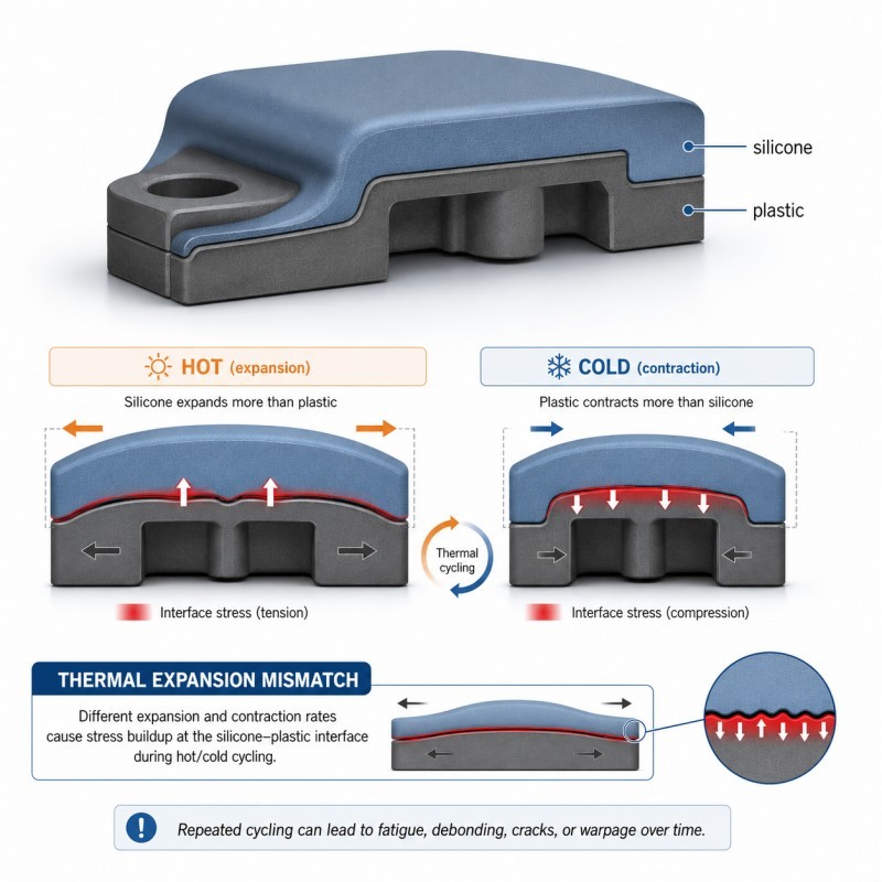
Silicone, plastic, metal, FPC, adhesives, coatings, terminals, and electronic components can expand and contract differently when temperature changes. Repeated dimensional mismatch can generate stress at bonded interfaces and eventually contribute to thermal-fatigue failure.
Silicone itself may remain flexible across a broad temperature range, but the complete overmolded assembly can still fail when the substrate, bonding structure, geometry, assembly force, and test conditions are not evaluated together.
For engineers, quality teams, and OEM buyers, the critical question is not only:
“Can the part survive one high-temperature test?”
The more important question is:
“Can the complete silicone-substrate interface withstand repeated expansion and contraction throughout the required product life?”
Answer Excerpt
LSR overmolded parts may crack or delaminate after thermal cycling because silicone and the plastic, metal, FPC, cable, or electronic insert do not expand and contract in exactly the same way.
Repeated temperature changes can concentrate shear, peel, and tensile stress around insert edges, bonding boundaries, sharp corners, thin silicone sections, holes, mechanical locks, and rigid-to-flexible transitions.
Failures are more likely when the substrate deforms, the bonding area is too narrow, the silicone thickness changes suddenly, curing is unstable, surface preparation is inconsistent, assembly preload is excessive, or the thermal-cycle test exceeds the design conditions.
Reliable performance requires the material combination, bonding method, mechanical retention, geometry, molding process, assembly, and validation plan to be reviewed as one complete system.
1. What Does Thermal Cycling Do to an Overmolded Part?
Thermal cycling repeatedly exposes a component to different temperatures.
A test may move the product between:
- High temperature and room temperature
- Low temperature and room temperature
- High temperature and low temperature
- Dry heat and humidity
- Heated operation and cold storage
- Rapid temperature shock
- Gradual temperature transition
During every cycle, the materials inside the component expand as temperature rises and contract as temperature falls.
If every material moved by exactly the same amount, the interface would experience less relative movement.
In an actual overmolded assembly, the materials may have different:
- Thermal-expansion behavior
- Stiffness
- Thickness
- Geometry
- Moisture absorption
- Residual stress
- Bonding characteristics
- Temperature resistance
- Cooling rate
- Structural support
The resulting movement may be very small during one cycle.
After dozens, hundreds, or thousands of cycles, however, repeated stress can weaken the interface or concentrate damage in a specific area.
2. Different Materials Expand and Contract at Different Rates
Thermal-expansion mismatch is a major reason bonded multi-material structures experience stress during temperature changes.
An LSR overmolded component may combine:
- Flexible silicone
- Rigid engineering plastic
- Stainless steel
- Aluminum
- Copper
- FPC
- Glass
- Ceramic
- Cable insulation
- Electronic components
- Surface coatings
Each material responds differently to temperature.
The silicone may deform and absorb some movement, while the rigid insert restricts it. Stress is then transferred into the silicone layer, bonding interface, mechanical-locking area, or insert itself.
The final stress depends not only on the materials but also on:
- Temperature range
- Heating and cooling rate
- Number of cycles
- Product dimensions
- Insert stiffness
- Silicone hardness
- Silicone thickness
- Bonding area
- Edge geometry
- Assembly restraint
Before tooling, engineers should review material compatibility together with the actual thermal environment rather than assuming that two materials are compatible only because they bond during the first sample trial.
3. Why Failure Often Starts at the Bonding Edge
The center of an overmolded area may remain stable while damage begins around the outer edge.
This happens because the bonding boundary is often where:
- The silicone layer ends
- The rigid substrate becomes exposed
- Wall thickness changes
- Assembly movement is concentrated
- Water can enter
- Peel stress begins
- Mold parting lines are located
- Surface treatment becomes inconsistent
- Mechanical locking ends
A wide bonded area under compression may remain stable.
A narrow exposed edge may experience a peeling force every time the materials expand or contract.
Possible early warning signs include:
- A thin white line at the edge
- Slight edge lifting
- A glossy or cloudy stress mark
- A small gap visible under magnification
- Local dirt or moisture entering the interface
- Reduced peel strength
- A crack that grows after each test cycle
Edge design should therefore be treated as an engineering feature, not merely a cosmetic boundary.
4. Plastic Inserts Can Warp, Shrink, or Relax
In silicone over plastic projects, failure may occur even when the silicone material itself remains acceptable.
Plastic inserts can change during:
- LSR molding temperature
- Post-curing
- Heat aging
- Thermal cycling
- Screw assembly
- Long-term storage
- Moisture exposure
- Mechanical loading
Plastic-related risks include:
- Warpage
- Loss of flatness
- Residual stress release
- Hole-position movement
- Groove deformation
- Local shrinkage
- Softening at high temperature
- Brittleness at low temperature
A small amount of plastic deformation can change the position of the silicone sealing lip or create stress around the bonding edge.
One side may be pulled away from the silicone while the opposite side becomes compressed.
Before mold development, the engineering review should confirm:
- Exact plastic grade
- Heat-deflection behavior
- Moisture condition
- Wall thickness
- Rib structure
- Insert flatness
- Existing plastic-molding stress
- Support inside the LSR mold
- Final assembly conditions
The plastic material name alone is not enough. Different grades of the same polymer family may behave differently during molding and thermal testing.
5. Metal Inserts Transfer Thermal Stress Differently
Silicone over metal components may use:
- Stainless steel
- Aluminum
- Copper
- Brass
- Nickel-plated parts
- Metal terminals
- Sensor probes
- Mounting plates
- Threaded inserts
Metal inserts usually maintain their dimensions more rigidly than flexible silicone, but their thermal movement can still place stress on the silicone interface.
Potential failure areas include:
- Sharp metal edges
- Corners
- Holes
- Threads
- Stamped burrs
- Thin metal plates
- Terminal roots
- Plating boundaries
- Areas with uneven silicone coverage
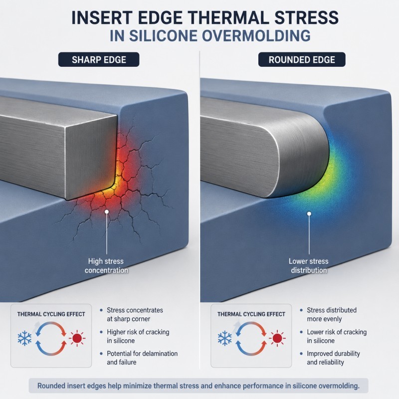
A sharp metal edge can concentrate stress and begin cutting or peeling the silicone from the inside.
A long metal insert may also create more total dimensional movement than a small insert during temperature changes.
Important design controls include:
- Rounded metal edges
- Burr removal
- Stable surface preparation
- Controlled plating
- Sufficient silicone coverage
- Wider bonding transitions
- Mechanical retention
- Avoiding extremely thin silicone near metal corners
Metal cleanliness and surface condition must remain consistent from sampling through mass production.
6. FPC and Electronic Inserts Need Flexible Transition Zones
FPC silicone overmolding presents additional thermal-cycling challenges because a flexible circuit may contain several materials in one thin assembly.
These may include:
- Polyimide film
- Copper traces
- Coverlay
- Adhesive layers
- Stiffeners
- Solder joints
- Components
- Connector pads
- Reinforcement material
Each layer can respond differently to temperature.
Possible thermal-cycle defects include:
- Silicone lifting near the FPC edge
- Cracks around a stiffener
- Copper-trace fatigue
- FPC bending-zone damage
- Component stress
- Contact-pad movement
- Loss of waterproof protection
- Silicone tearing around the cable exit
The transition from a rigid component or stiffener into a flexible FPC area is especially important.
The design should avoid forcing all movement into one narrow boundary.
Depending on the project, engineers may need to evaluate:
- Controlled bending radius
- Gradual silicone-thickness transition
- FPC support during molding
- Stiffener location
- Component temperature tolerance
- Low-temperature curing options
- Exposed contact-pad requirements
- Strain-relief geometry
Specialized LSR systems can support lower-temperature molding for sensitive electronics, which may provide additional design freedom when standard molding temperatures create unacceptable component risk.
7. Sharp Edges Create Stress Concentration
A rigid insert edge can act as a local stress concentrator.
During heating and cooling, the silicone repeatedly stretches and relaxes around this boundary.
High-risk structures include:
- Sharp plastic corners
- Stamped metal edges
- Narrow slots
- Small holes
- Thin silicone bridges
- Abrupt coverage boundaries
- Deep mechanical-locking holes
- Connector terminal roots
- FPC stiffener edges
Possible results include:
- White stress lines
- Local cracking
- Tearing
- Edge lifting
- Reduced bonding strength
- Water leakage
- Failure after repeated bending
A larger radius and smoother transition can distribute strain over a wider area.
During DFM review, engineers should evaluate both the external product shape and the hidden insert geometry underneath the silicone.
A finished product may look smooth on the outside while containing a sharp stress point below the surface.
8. Sudden Wall-Thickness Changes Increase Thermal Stress
A thick silicone section and a thin silicone section do not heat, cool, deform, or recover in exactly the same way.
Sudden thickness changes can create:
- Uneven curing
- Different cooling rates
- Local shrinkage
- Residual stress
- Distorted surfaces
- Concentrated stretching
- Weak transition zones
Typical high-risk areas include:
- Thick strain relief connected to a thin sealing membrane
- Thin silicone covering a thick metal insert
- Thick corner buildup around a narrow bonding edge
- Thin FPC protection beside a rigid connector
- Thick waterproof wall connected to a thin cosmetic layer
The design should use gradual transitions where the product function permits.
Before changing the silicone hardness, engineers should first determine whether the failure is caused by material selection or poor structural transition.
A harder silicone cannot automatically correct a stress concentration created by geometry.
9. Chemical Bonding Alone May Not Be Enough
Strong initial adhesion does not guarantee long-term thermal-cycle performance.
Chemical bonding may be influenced by:
- Substrate type
- Exact substrate grade
- Surface energy
- Surface cleanliness
- Primer
- Plasma treatment
- Bonding-layer thickness
- Curing temperature
- Storage before molding
- Contamination
- Environmental exposure
A sample may have strong initial peel resistance but gradually weaken after repeated thermal movement.
For demanding applications, chemical bonding may need to be supported by physical retention.
However, mechanical retention should not be added without structural evaluation. A locking feature can improve resistance to edge lifting, but a poorly designed feature may also concentrate stress or weaken the insert.
The design should determine whether the project needs:
- Chemical bonding
- Mechanical locking
- Wraparound retention
- Compression retention
- A combination of several methods
10. Mechanical Locking Can Help—but It Must Be Designed Correctly
Mechanical locking features may include:
- Holes
- Grooves
- Slots
- Ribs
- Undercuts
- Wraparound edges
- Cross-holes
- Dovetail structures
- Perforations
These features allow cured silicone to physically anchor around or through the insert.
Well-designed mechanical locking can help:
- Reduce edge lifting
- Improve retention
- Support the bonding interface
- Maintain silicone position
- Improve resistance to repeated movement
However, a locking feature can also create new risks when it contains:
- Sharp corners
- Very thin insert walls
- Excessively small holes
- Incomplete silicone filling
- Trapped air
- Weak silicone bridges
- Difficult demolding
- Stress concentration
Mechanical locking should distribute load rather than move the entire load into one small hole or undercut.
The locking design must be reviewed together with:
- Silicone flow
- Venting
- Insert strength
- Wall thickness
- Bending direction
- Temperature range
- Bonding performance
- Mold feasibility
11. Residual Stress May Already Exist Before Testing
Some components enter thermal-cycle testing with stress already built into the product.
Residual stress can result from:
- Insert deformation during molding
- Silicone shrinkage
- Uneven curing
- Uneven cooling
- Excessive injection pressure
- Forced demolding
- Misaligned assembly
- Screw tightening
- Packaging deformation
- FPC tension
LSR is injected into a heated mold and cured inside the cavity. Material flow, heating, curing, mold sealing, and part geometry therefore need to be controlled together during production.
A product containing high residual stress may pass room-temperature inspection because the damage has not yet become visible.
Thermal cycling can repeatedly add and remove stress until the weakest area begins to crack or separate.
Failure analysis should therefore review both the thermal test and the complete manufacturing history.
12. Curing Conditions Affect Long-Term Interface Performance
LSR curing conditions influence the final mechanical and bonding characteristics.
Important process variables include:
- A/B component ratio
- Mixing quality
- Mold temperature
- Curing time
- Insert temperature
- Silicone thickness
- Cycle stability
- Material storage
- Primer drying
- Surface-treatment timing
- Post-curing, when required
Possible problems caused by unstable processing include:
- Inconsistent hardness
- Poor recovery
- Weak bonding
- Uneven shrinkage
- Local under-curing
- Surface variation
- Different results between cavities
A component can appear fully molded while still having inconsistent interface performance.
For mass production, the process should be controlled through defined parameters and production records rather than visual inspection alone.
13. Waterproof Failure May Appear Before Visible Delamination
A silicone-overmolded waterproof component does not need a large visible crack to fail.
A microscopic interface gap may allow:
- Water ingress
- Air leakage
- Moisture migration
- Saltwater penetration
- Cleaning-fluid penetration
- Condensation near electronics
A part may therefore fail an air-leak or immersion test before technicians can see any obvious delamination.
High-risk leakage paths include:
- Silicone-to-plastic boundaries
- Silicone-to-metal edges
- FPC exits
- Terminal roots
- Mechanical-locking holes
- Parting lines
- Thin sealing lips
- Areas with uneven compression
Waterproof testing should be performed after the required environmental conditioning, not only before thermal cycling.
The complete test sequence may include:
- Initial visual and dimensional inspection
- Initial leak or immersion test
- Thermal cycling
- Recovery period
- Reinspection
- Repeat leak testing
- Bonding or cross-section analysis
This is also why waterproof silicone seals may pass initial assembly but fail environmental reliability testing.
14. Moisture and Chemicals Can Compound Thermal Stress
Thermal cycling may not be the only environmental factor.
The component may also contact:
- Humidity
- Water
- Saltwater
- Automotive coolant
- Oil
- Cleaning agents
- Disinfectants
- Sweat
- Skin oils
- Cosmetics
- Industrial chemicals
Plastic materials may absorb moisture or change dimensions.
Chemical exposure may affect silicone, bonding layers, primers, coatings, or substrate surfaces.
A component that survives dry thermal cycling may behave differently during combined heat, moisture, and chemical exposure.
The buyer should define the real application environment before material and test approval.
Generic statements such as “temperature resistant” or “chemical resistant” are not enough for a precision overmolding project.
15. Assembly Preload Can Change the Thermal-Cycle Result
The same component can produce different test results depending on how it is assembled.
Assembly variables may include:
- Screw torque
- Fastening sequence
- Housing flatness
- Press-fit force
- Compression ratio
- Connector insertion force
- Cable routing
- FPC bending
- Assembly fixture
- Repeated disassembly
An overmolded seal that is already highly compressed may experience additional stress during heating.
A component installed at an incorrect angle may concentrate force on one edge.
A cable pulled tightly during assembly may transfer load directly into the silicone overmolding boundary.
For meaningful validation, thermal cycling should use the real or accurately simulated final assembly.
Testing a loose overmolded component may not reproduce the stresses present in the complete product.
16. Why Can Samples Pass While Mass Production Fails?
Development samples are often produced under close engineering control.
During sampling:
- Inserts may be carefully selected
- Surfaces may be cleaned individually
- Primer may be applied carefully
- Process parameters may be adjusted slowly
- Every part may be inspected
- Only one mold cavity may be evaluated
Mass production introduces additional variation:
- Different insert batches
- Surface contamination
- Multiple cavities
- Primer variation
- Operator changes
- Long continuous production
- Mold-temperature drift
- Material-batch changes
- Tool wear
- Packaging stress
- Assembly variation
A structure with very little design margin may pass several samples but become unstable when normal production variation is introduced.
Pilot production should therefore include samples from:
- Every mold cavity
- Different insert batches
- Different production periods
- Multiple assembly lots
- The beginning and end of a continuous run
Thermal-cycle validation should represent the real production process, not only specially prepared engineering samples.
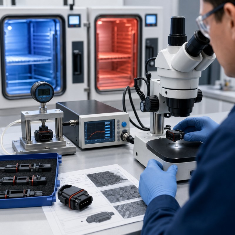
17. A Practical Thermal-Cycling Failure-Analysis Sequence
When an LSR overmolded component cracks or delaminates after thermal cycling, investigate the problem systematically.
Recommended sequence:
- Confirm the exact temperature range.
- Confirm heating and cooling rates.
- Confirm dwell time at each temperature.
- Record the number of completed cycles.
- Identify the first cycle at which failure appeared.
- Mark the exact crack or separation location.
- Compare passing and failing samples.
- Check whether the damage starts at an insert edge, parting line, hole, or locking feature.
- Review silicone thickness around the affected area.
- Inspect the substrate for warpage or dimensional change.
- Check surface preparation and bonding records.
- Review primer, plasma, or cleaning conditions.
- Compare mold cavities and insert batches.
- Inspect mechanical-locking structures.
- Review curing and molding parameters.
- Check assembly torque, compression, or cable preload.
- Perform microscopic or cross-section inspection when required.
- Repeat the test after changing one controlled variable.
Do not change material, geometry, primer, curing, and assembly conditions at the same time.
Changing one variable at a time makes it easier to identify the actual root cause.
18. What Should Be Validated Before Mass Production?
Before approving an LSR overmolded component for thermal-cycle service, buyers and manufacturers should confirm:
- Silicone material grade
- Silicone hardness
- Substrate material and exact grade
- Substrate moisture condition
- Temperature range
- Heating and cooling rate
- Cycle count
- Dwell time
- Recovery time
- Silicone wall thickness
- Insert-edge radius
- Bonding-area width
- Surface preparation
- Primer or plasma process
- Mechanical-locking structure
- Parting-line location
- Gate and venting locations
- Curing parameters
- Insert positioning
- Assembly preload
- Waterproof-test method
- Electrical-test method
- Acceptance criteria
- Pilot-production quantity
- Traceability requirements
Acceptance should not be based only on whether the silicone remains visibly attached.
Depending on the product, validation may also require:
- Peel or pull testing
- Edge-lifting inspection
- Air-leak testing
- Immersion testing
- Electrical continuity testing
- Dimensional measurement
- Cross-section inspection
- Repeated bending
- Assembly testing
How SiliconePlus Supports Thermal-Cycling Overmolding Projects
SiliconePlus provides custom liquid silicone injection molding and silicone overmolding services for components used in automotive electronics, sensors, 3C electronics, wearable devices, medical electronics, beauty devices, and industrial equipment.
Our project support can include:
- DFM and drawing review
- Substrate-material evaluation
- Silicone material and hardness selection
- Silicone over plastic
- Silicone over metal
- FPC silicone overmolding
- Bonding-area review
- Mechanical-locking design
- Insert-edge and wall-thickness review
- Custom mold development
- Insert-positioning design
- Surface-treatment coordination
- Sample and pilot production
- Dimensional and appearance inspection
- Waterproof and air-leak test coordination
- Thermal-cycle test coordination
- OEM/ODM mass production
With 25+ years of silicone manufacturing experience, our team supports projects from early structure review and mold development through sample validation and stable batch production.
For components exposed to high- and low-temperature cycling, we review the complete system:
- Silicone
- Plastic, metal, FPC, or electronic insert
- Bonding interface
- Mechanical retention
- Wall thickness
- Insert edges
- Assembly force
- Test conditions
- Production variation
The objective is not only to achieve strong bonding on the first sample.
The objective is to maintain structural, sealing, and functional performance after the required environmental cycles.
What Information Should Buyers Send for Evaluation?
To evaluate a thermal-cycling overmolding project, buyers should provide:
- 2D drawing
- 3D file
- Product or sample photos
- Substrate material and exact grade
- Silicone material requirement
- Silicone hardness
- Silicone coverage area
- Exposed functional areas
- Bonding requirement
- Mechanical-locking structure
- Working-temperature range
- Thermal-cycle test specification
- Heating and cooling rate
- Required cycle quantity
- Waterproof requirement
- Electrical requirement
- Assembly structure
- Known crack or delamination location
- Defect photos
- Estimated quantity
- Target production schedule
When a project has already failed, provide passing and failing samples, production-batch information, test records, and photos showing when the defect first appeared.
Frequently Asked Questions
Why does silicone delaminate only after several thermal cycles?
The initial bond may be strong enough for room-temperature inspection, but repeated expansion and contraction can gradually accumulate stress at the interface until the weakest area begins to separate.
Does thermal-cycle failure always mean the silicone material is wrong?
No. The cause may be substrate deformation, sharp insert edges, insufficient bonding area, unstable surface preparation, poor geometry, assembly preload, curing variation, or several factors working together.
Can softer LSR prevent thermal-cycle cracking?
Not automatically. Softer silicone may absorb movement more easily, but it may also stretch excessively, lose structural support, or move around the insert. Hardness must match the geometry and application.
Is chemical bonding enough for thermal-cycle applications?
It may be sufficient for some material combinations and operating conditions. Demanding projects may benefit from combining chemical bonding with suitable mechanical retention.
Can mechanical locking completely prevent delamination?
No. Mechanical locking can improve retention, but it does not correct contamination, poor curing, substrate deformation, sharp stress concentrations, or unsuitable test conditions.
Why does cracking often begin near an insert corner?
Sharp corners and sudden transitions concentrate movement into a small area. Repeated thermal expansion and contraction can then produce local fatigue, whitening, tearing, or edge lifting.
Should thermal cycling be performed before waterproof testing?
Many reliability plans include initial waterproof testing, thermal cycling, and repeat waterproof testing. The exact sequence and acceptance criteria should match the final product requirement.
Can FPC silicone overmolding survive thermal cycling?
It can when the FPC structure, stiffener, components, silicone boundary, bending zone, curing conditions, and test requirements are properly designed and validated.
Conclusion
LSR overmolded parts can crack or delaminate after thermal cycling because silicone and the substrate do not respond to temperature changes as one uniform material.
Thermal-expansion mismatch, sharp insert edges, sudden wall-thickness changes, substrate deformation, weak bonding boundaries, unstable curing, residual stress, assembly preload, moisture, and production variation can all contribute to failure.
The most reliable approach is to review the complete multi-material structure before tooling and validate it through controlled samples, pilot production, thermal cycling, functional testing, and post-test inspection.
If you are developing a silicone over plastic, silicone over metal, FPC, connector, sensor, or waterproof electronic component for high- and low-temperature service, contact SiliconePlus and send us your drawings, substrate material, silicone requirement, thermal-cycle conditions, assembly structure, failure photos, testing requirements, and estimated quantity. Our engineering team will review the project and provide practical manufacturing recommendations.