Why Do Silicone Overmolded Cable Strain Reliefs Fail Pull and Bend Tests?
Answer Excerpt
Silicone overmolded cable strain reliefs usually fail because bending or pulling force is concentrated at one narrow transition between the flexible cable and the rigid overmolded section. Reliable performance requires a gradual flexibility transition, stable cable positioning, sufficient silicone thickness, suitable hardness, controlled adhesion or mechanical retention, and a test method that represents the actual product load direction.
Silicone cable overmolding can combine strain relief, waterproof sealing, electrical insulation and mechanical protection into one molded component.
However, simply covering a cable with more silicone does not automatically improve durability.
If the overmolded section is too rigid, too short or poorly bonded, repeated bending transfers stress directly to the cable jacket, internal conductors or silicone termination edge.
The component may look acceptable after molding but fail during pull testing, repeated bending, torsion, vibration or long-term field use.
For cable assemblies used in vehicles, sensors and waterproof electronics, custom automotive silicone solutions should be reviewed together with the cable, connector and final installation structure.
What Failure Symptoms Appear During Pull and Bend Testing?
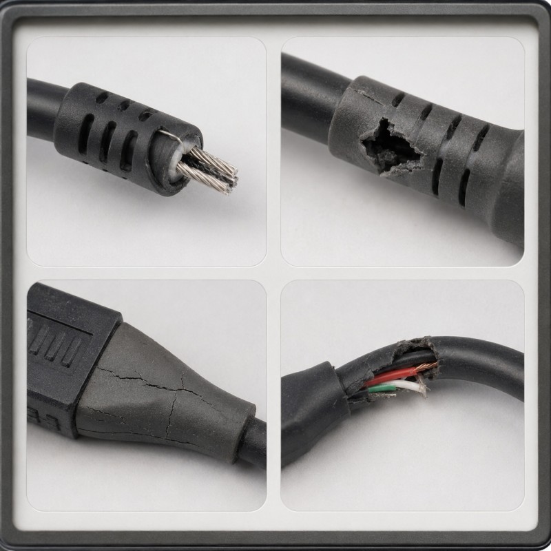
Cable strain-relief failures do not always appear in the same location. The failure pattern can help identify whether the main problem is adhesion, geometry, cable construction or molding-process variation.
The Cable Pulls Out of the Silicone
The cable jacket separates from the silicone overmold and slides out under tensile loading.
Possible causes include weak material compatibility, surface contamination, insufficient encapsulation length or missing mechanical retention.
The Silicone Tears at the Exit Edge
A crack starts where the cable leaves the molded strain relief.
This normally indicates that bending stress is concentrated at an abrupt, excessively thin or poorly radiused transition.
The Cable Jacket Cracks
The silicone remains intact, but the original cable jacket cracks near the molded boundary.
This suggests that the strain relief is too rigid or that bending force has been transferred to one narrow section of the cable.
Internal Conductors Break
The outside of the cable may still look acceptable while copper conductors, signal wires or shielding fail internally after repeated bending.
This can happen when the bend radius is too small or when the bending zone is not controlled.
The Overmold Peels from the Connector Housing
The strain relief remains attached to the cable but separates from the plastic or metal connector body.
This indicates that the connector-side bonding or mechanical-locking structure is insufficient.
Leakage Appears After Bending
The assembly may pass an initial waterproof test but leak after cable bending, pulling or torsion.
This usually means that mechanical loading has opened an interface, damaged the silicone seal or changed the cable position.
Why Do Silicone Overmolded Cable Strain Reliefs Fail?
A strain relief fails when the mechanical load is not distributed gradually from the flexible cable into the more rigid connector or electronic housing.
The main engineering causes include:
• An abrupt stiffness transition
• Insufficient bend radius
• Excessive silicone hardness
• Incorrect silicone thickness
• Weak adhesion to the cable jacket
• Missing mechanical retention
• Unstable cable positioning
• Local air traps or short shots
• Cable-diameter variation
• Connector-side bonding failure
• Pull and bend tests that do not represent actual use
The cable, silicone overmold, connector body and final assembly should therefore be treated as one mechanical and sealing system.
1. The Flexibility Transition Is Too Abrupt
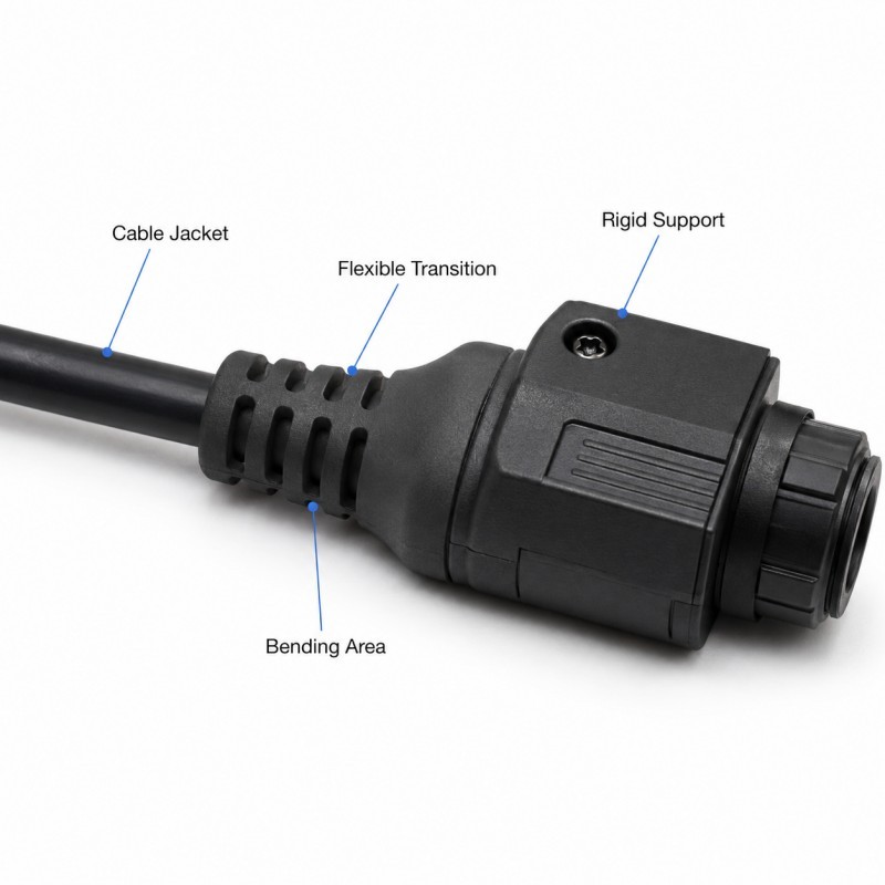
A cable is flexible, while a connector housing and a thick silicone overmold are comparatively rigid.
If the strain relief changes suddenly from a thick rigid section to an unsupported cable, bending stress becomes concentrated at the exit edge.
This stress concentration can cause:
• Silicone tearing
• Cable-jacket cracking
• Conductor fatigue
• Interface peeling
• Leakage after repeated bending
A better design uses a gradual flexibility transition.
The silicone thickness, rib height or outer diameter should reduce progressively toward the free cable section instead of ending with a sharp step.
The transition should also include a suitable radius rather than a sharp corner.
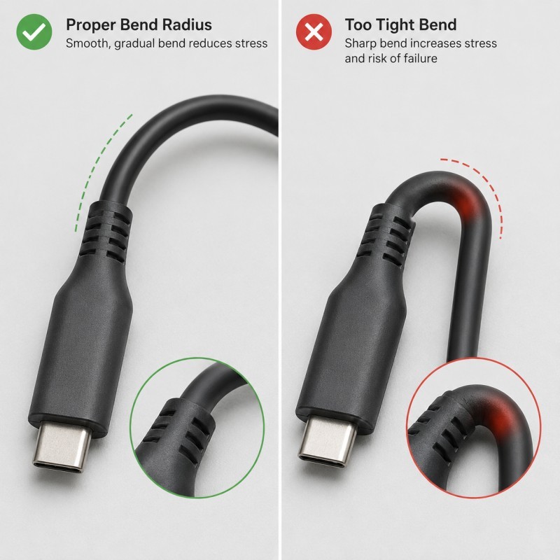
2. The Bend Radius Is Too Small
Every cable assembly has a minimum practical bend radius.
When the strain relief forces the cable to bend too tightly, the cable jacket, shielding, conductors and internal insulation experience higher mechanical strain.
A small bend radius may produce:
• Jacket whitening
• Permanent cable deformation
• Copper-conductor fatigue
• Shielding damage
• Signal instability
• Reduced service life
The required bend radius depends on cable diameter, conductor construction, shielding, jacket material and expected movement.
It should be confirmed with the cable supplier and validated on the complete molded assembly.
The design should not rely on one universal bend-radius value for every cable.
3. Silicone Hardness and Thickness Are Not Balanced
Silicone hardness and wall thickness together determine how the strain relief bends.
A softer silicone does not automatically create a better strain relief. If the wall is too thin, the part may tear, deform or fail to support the cable.
A harder silicone does not automatically improve pull strength. If the section is too thick, bending load may move directly to the cable exit.
Engineers should review:
• Silicone hardness
• Root thickness
• Exit thickness
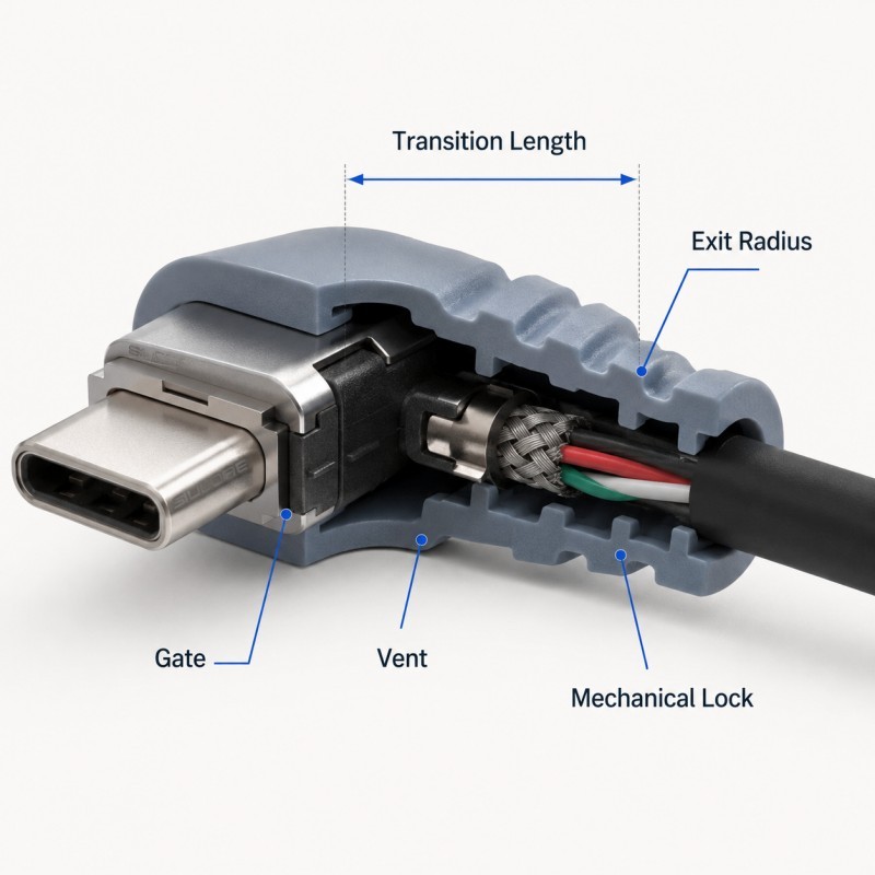
• Transition length
• Rib geometry
• Cable diameter
• Expected pull force
• Expected bending direction
• Operating temperature
The strain relief should be flexible enough to distribute bending but strong enough to resist tearing, cable pull-out and permanent deformation.
4. The Cable Jacket Does Not Bond Reliably to Silicone
Cable jackets may be manufactured from different plastics or elastomers, and not every jacket material forms a reliable chemical bond with liquid silicone rubber.
Bonding can also be affected by:
• Surface lubricants
• Processing oils
• Release agents
• Dust
• Moisture
• Ink or printed markings
• Jacket additives
• Cable-supplier changes
• Material-lot variation
The exact cable specification must be confirmed before tooling.
The same cable color and diameter do not guarantee that the jacket formulation is unchanged.
Where chemical adhesion is uncertain, the design should include mechanical retention instead of depending only on surface bonding.
Plastic with silicone overmolding should be validated using the exact substrate and silicone combination planned for mass production.
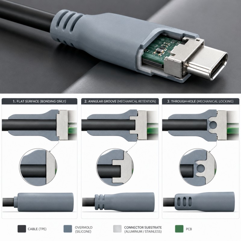
5. Mechanical Retention Is Missing or Too Weak
Mechanical retention allows the cured silicone to lock around the cable, connector insert or housing.
Possible retention features include:
• Connector-housing grooves
• Through-holes
• Circumferential ribs
• Undercut channels
• Edge wraparound
• Cable-jacket texture
• Controlled encapsulation length
• Internal anchors
Mechanical retention is especially important when:
• Cable-jacket adhesion is uncertain
• High pull loads are expected
• Repeated torsion occurs
• The product is used outdoors
• Leakage would cause electrical failure
• The cable supplier may change
Retention geometry must still allow complete LSR filling and venting.
A deep groove that traps air or creates a short shot can weaken the assembly instead of improving it.
6. Cable Positioning Is Not Stable During Molding
The cable must remain centered and stable during mold closing and LSR injection.
If the cable shifts, the overmold thickness becomes uneven.
Possible results include:
• Thin silicone on one side
• Excessive silicone on the opposite side
• Off-center strain relief
• Weak pull performance
• Unstable bending direction
• Cable-jacket damage
• Poor mold shut-off
• Silicone flash
Cable positioning may use:
• Dedicated cable grooves
• Clamp fixtures
• Connector datums
• Support blocks
• Controlled cable tension
• Loading trays
• Camera confirmation
• Automated insert loading
The fixture should locate the cable without crushing the jacket or creating permanent deformation.
7. Gate and Venting Create Local Weak Areas
Gate position determines how LSR flows around the cable and connector insert.
An unsuitable gate may:
• Push the cable out of position
• Create uneven filling
• Trap air near the cable
• Form weld lines
• Leave thin weak sections
• Create visible gate marks
• Increase local cavity pressure
Venting should be provided at final fill locations and around mechanical-retention structures.
Air trapped between the cable jacket and silicone may create a hidden void that later becomes a crack or leakage path.
The gate, vent, cable support and demolding direction should be reviewed together during mold DFM.
What Does a Reliable Cable Strain-Relief Structure Look Like?
A reliable cable strain-relief structure normally includes several coordinated features.
Stable Connector-Side Support
The strain relief should be securely connected to the connector housing, insert or protected electronic device body.
Mechanical Retention
Grooves, holes, wraparound features or anchors should prevent the silicone from being pulled away from the rigid structure.
Gradual Flexibility Transition
The molded section should reduce gradually from the rigid root toward the free cable.
Controlled Bend Direction
Where the application has a predictable movement direction, the strain relief can guide bending instead of allowing a sharp random fold.
Sufficient Encapsulation Length
The cable should have enough overmolded length to distribute pull force and support the cable jacket.
Smooth Surface Transition
Sharp notches, thin corners and sudden section changes should be avoided.
Stable Cable Centering
The cable should remain centered so that silicone thickness is consistent around its circumference.
Manufacturable Gate and Venting
The structure should fill completely without moving the cable or trapping air.
DFM Checklist for Silicone Cable Overmolding
| DFM Item | What Engineers Should Confirm |
Cable specification | Exact supplier, jacket material, diameter and construction are confirmed |
Connector structure | The rigid support and overmold interface are defined |
Pull direction | Expected tensile load and direction are known |
Bend direction | Expected movement and bending plane are defined |
Bend radius | The complete cable assembly can meet the required radius |
Silicone hardness | Hardness matches the required flexibility and strength |
Wall thickness | Root, transition and exit thickness are manufacturable |
Transition length | Stiffness changes gradually rather than abruptly |
Bonding method | Adhesion, primer, treatment or mechanical lock is defined |
Cable positioning | The cable remains centered during molding |
Mold shut-off | The jacket is sealed without crushing or flash |
Gate position | Flow does not push the cable out of position |
| Venting | Air can escape from final-fill and retention areas |
| Demolding | Part removal does not tear the transition edge |
| Test plan | Pull, bend, torsion and environmental conditions are defined |
The silicone mold design and tooling review should be completed using the cable drawing, connector model, jacket specification, expected movement and required test conditions.
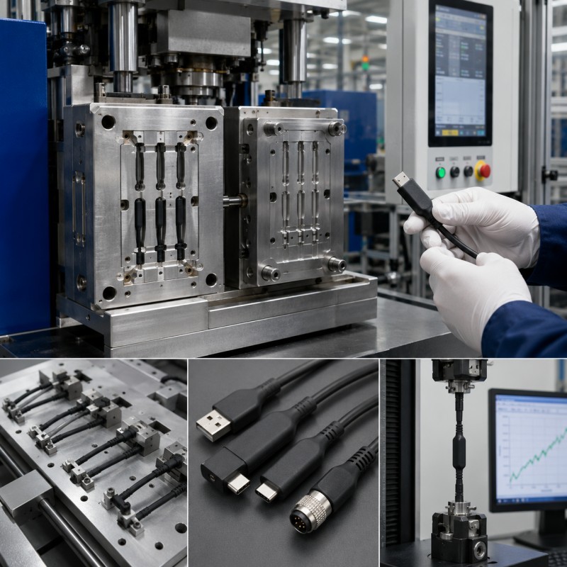
How Should Silicone Overmolded Cables Be Tested?
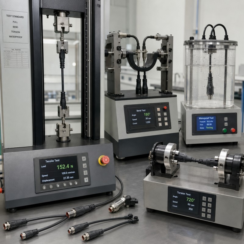
Testing should represent the actual mechanical and environmental conditions of the final product.
1. Pull Test
Apply tensile force in the intended service direction.
Record:
• Maximum force
• Displacement
• Failure position
• Cable pull-out
• Silicone tearing
• Connector damage
• Cable-jacket damage
The fixture must not create an unrealistic load path.
2. Repeated Bend Test
Define:
• Bend angle
• Bend radius
• Cycle count
• Bending speed
• Direction
• Applied cable load
• Test temperature
Inspect the cable after testing for cracks, conductor failure, interface separation and electrical instability.
3. Torsion Test
Rotate the cable around its axis to evaluate whether twisting causes jacket separation, silicone cracking or connector-side loosening.
4. Electrical Test
Check continuity, resistance, signal quality or functional performance before and after mechanical testing.
5. Leak Test
For waterproof cable assemblies, repeat the agreed air-leak or water test after pull, bend and torsion testing.
6. Thermal Cycling
Evaluate whether different thermal expansion between the cable, silicone and connector creates cracking, warpage or delamination.
7. Humidity and Fluid Exposure
Test the assembly after exposure to relevant water, humidity, oils, cleaners, sweat or application-specific fluids.
8. Pilot Production
Do not approve the structure based on one good sample. Consecutive production cycles should confirm cable positioning, appearance, pull performance and test consistency.
Common Failures and Recommended Corrective Actions
| Failure Symptom | Likely Cause | Recommended Action |
Cable pulls out | Weak bonding or no retention | Add mechanical locks and controlled encapsulation length |
Silicone tears at exit | Abrupt transition or small radius | Increase radius and extend the flexibility transition |
Jacket cracks | Strain relief is too rigid | Reduce local stiffness and review bend direction |
Internal conductor fails | Bending concentrates in one zone | Increase bend radius and guide the load path |
Overmold peels from housing | Weak connector-side retention | Add grooves, holes or edge wraparound |
| Flash appears around cable | Poor shut-off or cable variation | Improve positioning and shut-off allowance |
| Voids form near cable | Trapped air or contamination | Improve venting and incoming cable control |
| Leakage appears after bending | Interface or seal path opens | Improve retention and repeat leak testing after mechanical loading |
Typical Applications
Silicone overmolded cable strain reliefs are used where electrical connections require flexibility, sealing and mechanical protection.
Automotive Electronics
• Sensor cables
• Battery-system wiring
• Charging-port cables
• Motor and inverter connections
• Waterproof wire-harness interfaces
Consumer Electronics
• Charging cables
• Wearable-device cables
• Earphone and audio cables
• Camera and sensor assemblies
• Waterproof electronic modules
Medical and Healthcare Devices
• Monitoring cables
• Diagnostic sensor cables
• Handheld-device cables
• Patient-contact electronic assemblies
Industrial Equipment
• Outdoor sensor cables
• Robotics wiring
• Waterproof control cables
• Measurement equipment
• Vibration-resistant connectors
The final material, test conditions and compliance requirements should always be confirmed according to the specific application.
How SiliconePlus Supports Cable Overmolding Projects
SiliconePlus supports cable and connector overmolding projects from drawing review and DFM through tooling, sampling, testing and mass production.
Project support can include:
• Cable and jacket specification review
• Connector and insert structure review
• Strain-relief transition analysis
• Mechanical-retention design
• Cable-positioning fixture design
• Mold shut-off review
• Gate and venting review
• Silicone hardness and thickness evaluation
• Precision mold manufacturing
• LSR injection molding
• Dimensional and appearance inspection
• Pull and bend test coordination
• Waterproof test support
• Prototype and pilot production
• OEM and ODM mass production
SiliconePlus has 25 years of silicone manufacturing experience, more than 6,000 developed silicone projects, in-house CNC and EDM mold-processing capability, liquid silicone injection equipment and precision measuring resources.
Specific pull force, bending life, tolerance and waterproof performance should be confirmed according to the actual cable, connector, material combination and agreed test method.
FAQ
Can LSR Be Overmolded Directly onto a Cable Jacket?
It may be possible, but compatibility depends on the exact jacket material, additives, surface condition and LSR grade. The actual cable should be tested before tooling approval.
Does a Softer Silicone Always Improve Cable Bending Life?
No. A softer material may improve flexibility, but an excessively thin or weak section may tear. Hardness, thickness and transition length must be evaluated together.
Why Does the Cable Break Just Outside the Overmold?
The strain relief may be too rigid or may end too abruptly, causing bending stress to concentrate at the cable exit.
Is Chemical Bonding Enough for Pull Strength?
Not always. Mechanical retention is recommended when jacket adhesion is uncertain or when high pull, torsion or environmental loads are expected.
How Long Should the Strain Relief Be?
There is no universal length. It depends on cable diameter, bend radius, silicone hardness, expected movement and available product space.
Should Pull Testing Be Completed Before or After Bend Testing?
Both sequences may be useful. The validation plan should represent actual use, and waterproof or electrical testing should be repeated after mechanical loading.
Why Do Samples Pass but Mass Production Parts Fail?
Possible causes include cable-lot variation, inconsistent positioning, mold wear, contamination, molding-process changes and operator-loading variation.
What Information Is Needed for Cable Overmolding DFM?
Provide the cable drawing, jacket material, connector model, required pull force, bend radius, movement direction, environmental conditions, waterproof requirement and expected production volume.
Conclusion
Silicone overmolded cable strain reliefs fail when pulling, bending or torsion loads are concentrated at one weak transition.
Reliable performance requires coordinated control of:
• Cable-jacket specification
• Silicone hardness and thickness
• Bend radius
• Transition length
• Mechanical retention
• Cable positioning
• Mold shut-off
• Gate and venting
• Pull and bend testing
• Environmental validation
The best time to solve these risks is during DFM, before tooling begins.
For a project-specific evaluation, send your cable drawing, connector model, jacket specification and pull or bend requirements to the SiliconePlus engineering team.