How Should LSR Overmolding Preserve Light Output in FPC LED Strip Assemblies?
Answer Excerpt
LSR overmolding for an FPC LED strip must protect the flexible circuit without unintentionally changing the LED light path.
Before tooling, engineers should decide whether light is intended to pass through the silicone layer or through a defined optical opening. The selected silicone grade must then be qualified for the actual LED wavelength, molded thickness and optical requirements. Layer geometry, surface condition, air entrapment, flash and LED positioning should also be reviewed.
The final evaluation should measure the assembled lighting product under its specified operating conditions. A silicone-covered LED strip should not be assumed to retain the same brightness, color or beam pattern as an uncovered LED assembly.
Why Does Light Output Need Its Own Design Review?
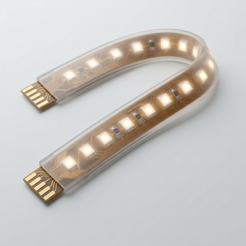
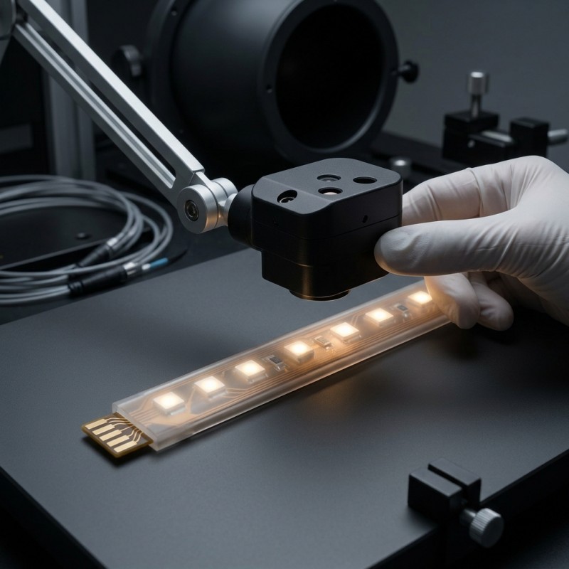
An FPC LED strip combines a flexible printed circuit, LED components and a silicone protection structure. LSR overmolding can integrate the protective layer with the flexible assembly, but the optical function introduces requirements that are different from ordinary circuit encapsulation.
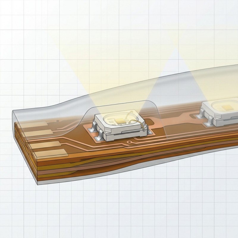
A silicone layer may sit directly in front of an LED, surround the LED package, or stop around a defined light-emitting area. Each arrangement creates a different optical path.
If the silicone is not selected and designed for that path, the finished assembly may show changes in:
- Light transmission
- Brightness distribution
- Color appearance
- Beam shape
- Light diffusion
- Visual consistency between LED positions
These effects depend on the silicone grade, layer thickness, surface geometry, LED package and operating conditions. They should be evaluated rather than assumed.
The website's existing custom silicone-overmolded FPC LED strip product page confirms the FPC, liquid silicone and LED material combination and the liquid silicone injection molding process. It does not specify a project-independent optical transmission value or guarantee a particular finished light output. Those requirements must be defined for each customer design.
Should the LED Emit Through Silicone or Through an Optical Opening?
The first optical design decision is whether the silicone itself forms part of the light path.
Two broad architectures can be considered.
1. Light passes through the silicone.
In this arrangement, the LED emits through a silicone region that covers or protects the light-emitting area. The selected silicone must have optical properties suitable for the intended wavelength and molded thickness.
The design review should consider transmission, haze, refractive behavior, color stability and the effect of the final molded surface. A material described simply as LSR is not automatically suitable for an optical application.
2. Light exits through a defined optical opening.
In this arrangement, the silicone protects the surrounding FPC and LED assembly while a designated optical area remains open or uses a separate optical element. The mold must control the boundary around that area without leaving flash, contamination or unintended silicone coverage.
Neither architecture is universally better. The correct choice depends on the LED package, optical design, environmental protection requirement, available space, assembly structure and material qualification.
The architecture should be agreed before tooling. Changing from an exposed optical area to a silicone-covered optical area after the mold has been designed may require changes to the material, cavity geometry and validation plan.
| Design approach | When it may be considered | Main engineering review |
| Light passes through silicone | The protective layer is intended to cover the LED's optical path | Optical transmission, haze, refractive behavior and molded thickness |
| Defined optical opening | The light-emitting area must remain uncovered or use a separate optical element | Opening geometry, alignment, flash control and environmental protection |
| Localized optical region | Only selected LED areas require a controlled optical material or geometry | Boundary position, material transition and output consistency |
How Should the Optical Exit Area Be Defined?
The optical exit area should be identified on the product drawing and 3D model before mold development. A general instruction such as “keep the LED visible” is not sufficient for a precision overmolding project.
The engineering drawing should distinguish the following zones:
1. LED light-emitting area.
Identify the actual emitting surface and its relationship to the silicone layer or optical opening.
2. Optical coverage zone.
Show where silicone is permitted to sit in the light path. If the silicone is intended to transmit light, specify the required material and optical evaluation criteria.
3. FPC protection zone.
Identify the circuit areas that require silicone coverage for the intended mechanical or environmental protection function.
4. Electrical contact and connection zones.
Mark the pads, connector contacts, test points and other electrical interfaces that must remain accessible.
5. Mounting and locating references.
Identify the rigid or repeatable features used to position the FPC and the finished strip in its final device.
6. Bending or routing areas.
Show where the FPC must flex or follow a defined route. The silicone coverage should not unintentionally prevent the required movement.
A complete coverage map helps the tooling team separate the optical, electrical and mechanical requirements. For related process planning, review our FPC with silicone overmolding manufacturing solutions.
How Should LSR Material Be Qualified for the LED Wavelength?
Material selection should start with the actual LED output and the intended optical path, not with the assumption that every silicone material is transparent.
Some silicone materials are developed for optical applications, while other LSR grades are selected primarily for sealing, insulation, cushioning or general protection. Their optical properties should not be treated as interchangeable.
Before approving the material, request and review the relevant supplier information:
- Optical transmission data across the LED's relevant wavelength range
- The test thickness used to generate the optical data
- Refractive-index information where it affects the optical design
- Clarity, haze or color information where applicable
- Available aging information relevant to light, heat and the product environment
- Hardness and flexibility requirements
- Adhesion or retention suitability for the actual FPC construction
- Compatibility with the proposed molding and curing process
A transmission value measured at one wavelength and one test thickness should not automatically be applied to another LED, silicone thickness or finished geometry.
The FPC, LED package, soldered components, coverlay and any adhesive layers must also be reviewed against the proposed molding process. The material system should be evaluated as a complete assembly.
For process feasibility, discuss the actual LED/FPC structure and material requirements with the team responsible for the liquid silicone injection molding capability.
Material item | Why it matters | What buyers should provide or request |
Optical transmission | Determines how much light passes through the selected material | Supplier data for the relevant wavelength and test thickness |
Refractive behavior | May influence light extraction, direction and distribution | Material data and optical design requirements |
| Haze and clarity | Can affect diffusion and visual appearance | Required appearance and measurement method |
Color stability | Material appearance may change during product use | Relevant light, heat and environmental exposure requirements |
| Hardness and flexibility | Must match the mechanical and assembly design | Target feel or deformation requirement, if specified |
| FPC compatibility | The complete material stack must tolerate the molding process | FPC stack-up, LED package and adhesive information |
| Bonding or retention | The silicone must remain in its intended position | Substrate details and interface requirements |
How Do Silicone Thickness and Surface Geometry Affect the Light Path?
The silicone layer is both a protective structure and, in some designs, an optical element. Its thickness and surface geometry should therefore be reviewed against the required light output.
A thicker layer is not automatically better or worse. Its effect depends on the selected silicone, LED wavelength, surface finish, geometry and optical architecture.
Key design points include:
1. Layer thickness.
Where light passes through silicone, the actual molded thickness should be included in material qualification and optical testing. A material data sheet based on a thin test specimen may not represent a thicker molded section.
2. Surface curvature.
A curved silicone surface may change the direction in which light exits. If the product requires a particular beam shape or viewing angle, the surface geometry should be reviewed with the optical design.
3. Local thickness transitions.
Sudden changes in silicone thickness may create different optical appearance or light distribution across the strip. Use controlled transitions where the product design permits.
4. LED-to-silicone spacing.
The distance between the LED emitting surface and the silicone surface can influence the final optical result. The relevant dimensions should be reviewed in the complete cross-section.
5. Surface texture.
A textured surface may diffuse light differently from a smooth surface. Texture should be selected according to the intended lighting effect, not added only for appearance.
6. Repeatability along the strip.
The same optical design should be evaluated at representative LED positions along the FPC. A visually acceptable area at one end does not establish uniformity across the complete assembly.
The optical design should be approved using molded samples made with the intended material and representative tooling conditions.
How Should the Mold Protect the Optical Zone?
The mold must form the required silicone protection structure without introducing defects into the optical exit area.
Potential molding risks include:
- Air bubbles or voids in the optical region
- Contamination trapped against the LED or silicone surface
- Flow marks that change the visible appearance
- Uneven filling around LED packages
- Flash extending into a defined optical opening
- Local thickness variation
- FPC movement that changes LED position
- Surface damage during demolding
The engineering review should consider the following controls.
1. Gate and flow direction.
Review how the LSR enters the cavity and moves around the LED packages. The flow strategy should avoid creating an uncontrolled fill pattern in critical optical areas.
2. Venting.
Air must be able to escape from the intended final-fill regions. Vent locations should be reviewed without creating flash at optical or electrical interfaces.
3. Mold surface condition.
The cavity surface that forms the optical-facing silicone should be reviewed for the required finish and cleanliness.
4. FPC positioning.
The FPC must remain in its intended position during mold closing, filling, curing and demolding. LED position changes can affect the relationship between the emitting surface and the silicone layer.
5. Flash control.
The mold should define the boundary between silicone-covered regions and any optical or electrical areas that must remain exposed.
6. Demolding.
The finished strip should be released without damaging the silicone surface, moving the FPC or stressing the LED package.
These items should be reviewed as part of the silicone mold design capabilities and the project-specific DFM process.
Potential defect | Possible optical or functional effect | Review focus |
Bubble or void | Local scattering or visible optical inconsistency | Filling, venting and material handling |
Contamination | Visible marks or reduced optical clarity | FPC cleanliness, mold cleanliness and handling |
| Uneven silicone thickness | Different light transmission or appearance across the strip | Cavity geometry and dimensional inspection |
Flash near an optical opening | Partial obstruction of the intended light path | Shut-off and boundary design |
| FPC or LED movement | Misalignment between the LED and optical region | Insert locating and support |
| Surface damage | Changed appearance or light distribution | Mold finish and demolding method |
| Incomplete filling | Missing or irregular silicone coverage | Gate, vent and filling review |
How Should Thermal and Electrical Interfaces Be Managed?
An FPC LED strip has optical, electrical and thermal requirements. The silicone coverage plan should not solve one requirement by creating a problem in another.
LEDs generate heat during operation. The product designer should identify how heat leaves the LED package and travels through the complete device. The LSR layer should not automatically be treated as a heat sink or as a substitute for a designed thermal interface.
Before tooling, review:
1. LED operating conditions.
Provide the intended operating current, power conditions and relevant temperature requirements for the actual LED assembly.
2. Thermal contact areas.
Identify any heat-transfer surfaces, metal supports or other thermal interfaces that must remain exposed or maintain direct contact with another component.
3. Silicone coverage near heat-sensitive areas.
Check whether the proposed silicone layer changes the intended thermal path or creates an unwanted insulating layer between mating surfaces.
4. Electrical interfaces.
Keep required contact pads, connector areas, test points and other electrical features accessible and free from unintended silicone coverage.
5. Component process limits.
Confirm that the FPC, LED package, solder joints and other assembled materials can tolerate the actual LSR molding and curing process.
6. Final device assembly.
Evaluate the strip in the housing or mounting arrangement in which it will operate. A loose LED/FPC sample may not represent the final thermal or optical condition.
Where a project requires thermal performance from a silicone material, the specific material data and complete assembly must be reviewed. Do not assume that a general-purpose LSR grade provides a particular thermal conductivity.
How Should the Finished LED Assembly Be Validated?
Optical validation should be performed on representative overmolded samples and, where possible, in the final device assembly.
The test method should reproduce the customer's specified operating conditions. LED current, power input, ambient conditions, mounting position and measurement setup should be controlled so that results can be compared.
A practical validation plan may include:
1. Visual inspection.
Check the optical surface for bubbles, voids, contamination, flash, scratches and visible variation.
2. Dimensional inspection.
Review silicone thickness, optical opening dimensions, LED position and the relationship between the FPC and molded coverage.
3. Optical measurement.
Use a suitable photometric method to evaluate the required light output, brightness distribution, color appearance or beam pattern.
4. Electrical function.
Verify circuit continuity and LED operation after overmolding. Check required contacts and connectors for accessibility.
5. Thermal evaluation.
Operate the assembled product under the customer's defined conditions and review the temperature behavior of the LED and surrounding structure.
6. Environmental evaluation.
If required, repeat the optical and electrical checks after the specified heat, humidity, UV exposure, vibration or other environmental conditioning.
7. Production repeatability.
Compare samples from representative production cycles and, where applicable, different mold cavities. The inspection method should be repeatable rather than relying only on subjective visual judgment.
For products exposed to changing temperatures, also review the relevant LSR overmolding thermal-cycling design considerations. The test conditions and acceptance limits must be defined by the customer for the actual application.
| Validation stage | Inspection item | Method or reference | Acceptance basis |
Incoming material | Silicone optical data and material identity | Supplier documentation and approved material specification | Customer-approved material |
Before molding | FPC, LED and contact-area condition | Visual and dimensional inspection | Approved FPC and LED drawings |
After molding | Optical surface and silicone coverage | Visual inspection under controlled lighting | Approved appearance criteria |
After molding | Layer thickness and optical opening | Dimensional measurement | Approved drawing |
Optical function | Light output and distribution | Customer-defined photometric method | Customer-defined optical requirements |
Electrical function | LED operation and circuit continuity | Electrical function test | Approved electrical requirements |
| Thermal function | Temperature behavior in operation | Test in representative assembly | Customer-defined operating limits |
| Environmental validation | Optical and electrical function after conditioning | Customer-defined environmental test | Agreed test protocol |
| Production validation | Repeatability across samples or cavities | Representative production inspection | Approved control plan |
What Should Buyers Include in an FPC LED Overmolding RFQ?
A complete RFQ helps the manufacturer evaluate the optical design and the LSR molding process together.
For a custom silicone-overmolded FPC LED strip, buyers should provide:
1. 2D drawing and 3D CAD model of the complete LED/FPC assembly.
2. FPC stack-up, base-film information and relevant dimensional tolerances.
3. LED package information, including the intended wavelength or color.
4. LED layout, pitch and the required emitting direction.
5. The proposed optical architecture: light through silicone or through a defined opening.
6. Required optical transmission, brightness, color or beam-distribution criteria, where specified.
7. Silicone coverage map and all areas that must remain exposed.
8. Required silicone material, hardness or optical grade, if already defined.
9. LED operating conditions and thermal requirements.
10. Electrical contact, test-point and connector information.
11. Intended mounting method and final housing structure.
12. Environmental requirements and the corresponding validation method.
13. Prototype quantity, estimated production quantity and project schedule.
14. Physical FPC or LED samples, if available.
If optical performance is critical, provide the existing LED output data or a reference sample. This helps the engineering team understand the intended result before tooling.
SiliconePlus can review drawings, material requirements, molding feasibility, sampling and production planning. For broader process information, see our custom silicone manufacturing capacity.
Frequently Asked Questions
Can standard LSR be used as an optical cover for an LED strip?
Not automatically. Optical suitability depends on the exact silicone grade, LED wavelength, molded thickness, surface geometry and required light output. The material supplier's optical data should be reviewed before tooling.
Does transparent silicone always produce better LED light output?
No. Transparency alone does not define the finished optical result. Refractive behavior, haze, thickness, surface shape, LED package and the intended beam pattern also matter. The complete design should be tested.
Can LSR be molded directly over an FPC LED assembly?
The product structure can be evaluated for LSR overmolding, but feasibility depends on the FPC stack-up, LED package, electrical interfaces, material compatibility, positioning and molding-process limits. The actual assembly drawing and samples should be reviewed before tooling.
Can silicone thickness change the brightness or color appearance?
It can influence light transmission, diffusion and the direction of emitted light. The effect depends on the material and geometry, so the intended molded thickness should be included in optical qualification.
How can bubbles or voids affect a silicone-overmolded LED strip?
Bubbles and voids in an optical region may create visible irregularities or change local light distribution. Gate, venting, material handling, mold cleanliness and inspection should be reviewed to reduce these risks.
Does silicone overmolding automatically provide a waterproof rating for the finished LED strip?
No. The silicone structure may support an environmental protection design, but the final rating depends on the complete FPC assembly, interfaces, housing, cable connections and the agreed system-level test. No rating should be claimed without the relevant validation.
What information is needed to quote an FPC LED overmolding project?
Provide the FPC and LED drawings, material stack-up, LED wavelength or color, intended light path, silicone coverage map, electrical keep-out areas, operating conditions, optical requirements, validation plan and estimated quantity. Physical samples are helpful when available.
Conclusion
A successful LSR-overmolded FPC LED strip must protect the flexible circuit while preserving the intended optical function.
The most important decision is whether light should pass through the silicone or exit through a defined optical opening. That choice determines the material data, layer geometry, mold controls and inspection requirements that need to be reviewed before tooling.
Engineers should also protect electrical interfaces, preserve the intended thermal path, control optical-zone defects and validate the finished assembly under its actual operating conditions.
The silicone material, LED package, FPC structure and final device should be treated as one integrated design. A good-looking overmolded strip is not, by itself, proof of acceptable light output or finished-product performance.
Discuss Your Custom FPC LED Overmolding Project
Developing a flexible LED strip, wearable lighting module or custom FPC assembly that requires LSR overmolding?
Send SiliconePlus your 2D drawing, 3D CAD model, FPC stack-up, LED package information, intended optical path, silicone coverage map and required validation criteria.
Our team can review the optical-zone layout, silicone material requirements, mold design and production feasibility before tooling.
For a drawing-based project discussion, contact SiliconePlus.