How Should Shaft Fits and Button Clearances Be Designed for LSR-Overmolded Surgical Handles?
Answer Excerpt
For an LSR-overmolded surgical instrument handle, the rigid plastic substrate should define the critical locating and assembly features, while silicone should cover only the intended grip areas.
Shaft interfaces, button openings, pivot holes, screw features and assembly datums must remain dimensionally functional after molding. Before tooling, engineers should define the silicone coverage boundary, locate and support the plastic insert, control mold shut-offs and specify post-molding inspection.
The final material combination and any cleaning or sterilization compatibility must be validated against the actual instrument design and its intended use conditions.
Why Can an Overmolded Grip Affect Functional Fit?
An LSR-overmolded surgical handle combines a rigid engineering-plastic core with a flexible silicone grip molded directly onto selected areas. The silicone provides the intended gripping surface, while the rigid substrate should normally carry the locating and assembly geometry.
A handle may look correct after molding but still create assembly problems if silicone enters a shaft interface, restricts a button opening, obstructs a pivot hole or covers a locating face. Flash, insert movement and an incorrectly defined silicone boundary can also affect the finished interface.
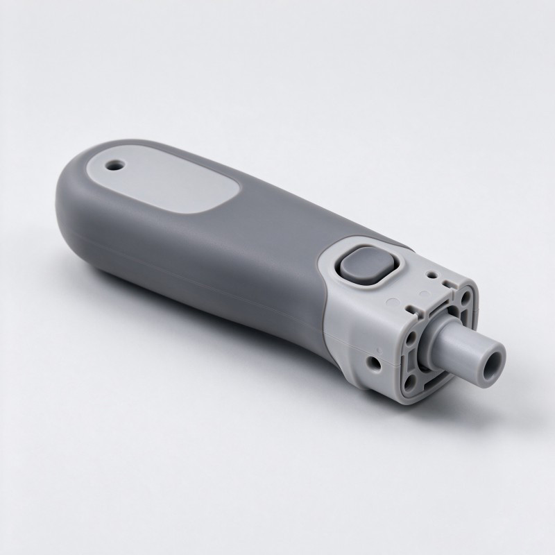
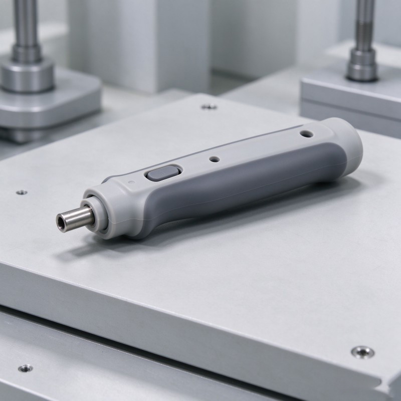
The SiliconePlus product page for a custom LSR overmolded surgical instrument handle identifies a high-temperature engineering-plastic substrate, an LSR insert-overmolding process and exposed buttons, shaft interfaces, holes and assembly areas.
This guide focuses on protecting these functional features during overmolding—not on general grip texture design or the design of a complete surgical instrument.
Which Features Must Remain Outside the Silicone Coverage?
The silicone coverage drawing should be reviewed together with the complete handle assembly drawing. Do not define the grip area only by appearance. Identify the features that control fit, movement, fastening and assembly.
Depending on the instrument design, the following interfaces may need to remain exposed:
1. Shaft interfaces and bores
These features may control engagement, alignment or connection to another instrument component. Their critical dimensions and locating relationships should be defined on the rigid substrate drawing.
2. Button openings and actuation areas
The silicone must not obstruct the button opening or interfere with the intended movement and access of the button. The required clearance should be defined from the actual button design.
3. Pivot holes and locking features
Where present, these features must remain open and correctly positioned so that the mating pin, pivot or locking component can be assembled and move as intended.
4. Screw holes and fastening surfaces
Silicone flash or unintended coverage can interfere with fastener installation, seating or access. These features should be included in the mold shut-off and inspection review.
5. Assembly datums and locating faces
The surfaces used to position the handle during assembly should remain identifiable and dimensionally controlled. A soft silicone surface should not unintentionally replace a rigid locating surface.
| Functional feature | Potential overmolding risk | Drawing or inspection requirement |
Shaft interface / bore | Silicone intrusion, flash or insert movement | Define critical dimensions and locating references |
Button opening | Restricted access or movement | Define opening boundary and required clearance |
Pivot hole | Obstruction or positional variation | Check hole exposure and position |
| Screw / fastening feature | Flash or blocked access | Define keep-out boundary and visual/functional inspection |
| Assembly datum | Silicone coverage or dimensional interference | Keep the rigid locating surface accessible |
| Silicone grip area | Incomplete or excessive coverage | Define intended coverage and edge boundary |
How Should the Plastic Insert Be Located During Molding?
Insert location should be established from stable features on the rigid plastic substrate. The mold should not rely on the soft silicone grip surface as the primary reference for positioning the handle.
Before tooling, review the following points:
1. Define the datum scheme.
Identify the rigid surfaces or features that control the shaft interface, button location and final assembly relationship. The datum structure must reflect how the handle is actually assembled and used.
2. Support the insert during molding.
The plastic component should be supported at suitable locations so that it does not shift or become distorted during the molding cycle. Avoid relying on thin unsupported walls or non-functional cosmetic areas as the only locating references.
3. Review insert variation.
Check the actual plastic grade, wall thickness, dimensional tolerance and possible warpage. These factors can influence how consistently the insert sits in the mold.
4. Confirm material and process compatibility.
The selected engineering plastic must be suitable for the intended LSR molding conditions. Material compatibility and bonding behavior should be evaluated using the actual resin grade and silicone system.
5. Define inspection references before sampling.
The same rigid datums used for design and tooling should be used to evaluate critical post-molding dimensions wherever practical.
For process planning, review the liquid silicone injection molding capability and discuss the actual substrate, drawing and molding requirements before approving tooling.
How Should Mold Shut-Off Protect Shaft and Button Areas?
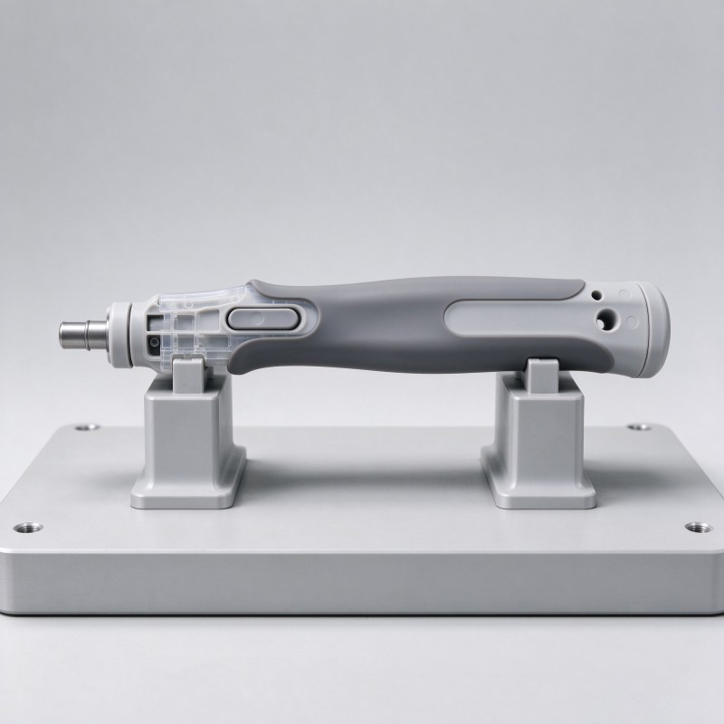
The silicone boundary must be defined as a manufacturable feature, not simply as a colored region in a product rendering.
For each functional interface, the engineering team should identify where silicone is allowed to reach and where the rigid plastic must remain exposed.
The mold shut-off should be designed around suitable rigid substrate surfaces. If the shut-off depends on an unstable or poorly supported area, insert variation or local gaps may allow silicone to enter a functional opening.
Important DFM checks include:
1. Coverage boundary definition.
Show the silicone coverage boundary clearly in the 3D model and identify critical exposed features on the 2D drawing.
2. Shut-off contact.
Review whether the mold can close consistently around shaft interfaces, button openings, holes and assembly faces.
3. Parting-line location.
Where practical, avoid placing the parting line directly across critical mating or locating surfaces. The final location must also consider demolding and mold construction.
4. Flash risk.
Review potential gaps caused by plastic tolerance, warpage, insert positioning and mold wear. Define how flash will be inspected and what is acceptable near each functional feature.
5. Flow and insert stability.
The filling path and venting arrangement should be reviewed so that the insert remains properly supported and air is not trapped around important molded areas.
For projects combining a rigid plastic insert and a silicone layer, see our silicone over plastic overmolding process and evaluate the shut-off structure during DFM.
Design risk | Possible consequence | DFM action |
Unclear silicone coverage boundary | Silicone reaches a functional feature | Define the boundary in 2D and 3D drawings |
| Unstable insert support | Position changes during molding | Locate from suitable rigid substrate features |
Incomplete shut-off contact | Flash near holes or mating surfaces | Review shut-off geometry and insert variation |
| Parting line across a critical interface | Raised edge or mismatch at a functional surface | Review parting-line location before tooling |
| Silicone edge too close to a moving feature | Possible interference with movement or assembly | Review the actual clearance and movement path |
| Undefined flash acceptance | Inconsistent sample approval | Agree on feature-specific inspection criteria |
How Should the Material Pair Be Qualified Before Tooling?
The plastic substrate and LSR should be evaluated as one material system. A material name alone is not enough to confirm that a combination is suitable for a particular molding project.
For a reusable surgical instrument handle, the project review should include:
1. Exact plastic grade.
Confirm the resin grade, relevant additives and dimensional behavior under the intended molding conditions. The product page identifies a high-temperature engineering-plastic substrate, but the exact resin grade must be specified for each project.
2. LSR grade and hardness.
Select the silicone according to the required grip feel, geometry, molding behavior and application conditions. Hardness should be agreed with reference to the actual handle design rather than selected from a generic recommendation.
3. Bonding or retention approach.
Evaluate whether the material pair can provide the required interface behavior. Chemical bonding, mechanical retention or a combination may be considered according to the actual substrate and geometry.
4. Cleaning and reprocessing conditions.
For reusable instruments, the customer should specify the intended cleaning, disinfection or sterilization process. The selected silicone, plastic and bonding system must be evaluated under those actual conditions.
5. Required documentation.
If a medical-grade LSR option is specified, confirm the exact material grade and the documentation required by the device manufacturer. The availability of a material option does not by itself establish regulatory compliance or suitability for every medical application.
SiliconePlus provides silicone mold design capabilities for custom structures. Material selection, functional requirements and tooling feasibility should be reviewed together before the design is frozen.
How Should the Finished Handle Be Inspected?
Inspection should confirm that the finished overmolded handle still performs its intended assembly and movement functions. Visual appearance alone is not enough to approve the part.
A practical inspection plan should separate rigid-substrate dimensions from flexible silicone features.
Before molding:
- Check the incoming plastic insert against the agreed drawing.
- Review relevant dimensions, warpage and critical locating features.
- Confirm the insert material and identification requirements.
During sampling:
- Verify that the insert is positioned correctly.
- Inspect the silicone coverage boundary.
- Check for flash around shaft interfaces, button openings, holes and assembly faces.
- Review whether the molded grip interferes with any intended movement or mating feature.
After molding:
- Measure critical shaft interfaces and assembly datums using an agreed reference method.
- Check button openings and required actuation clearance.
- Confirm that pivot holes, screw features and other specified openings remain accessible.
- Assemble the handle with the relevant mating component where an assembly check is required.
- Record any customer-defined functional, cleaning or reprocessing validation.
Inspection fixtures should reference the rigid substrate wherever practical. Excessive clamping or uncontrolled pressure on the soft silicone can distort the part and make measurements difficult to compare.
The OEM and manufacturer should agree on critical dimensions, inspection methods and acceptance criteria before sample approval. No universal tolerance should be assumed for every surgical handle design.
| Inspection stage | Item to review | Suggested verification approach | Acceptance basis |
Incoming insert | Plastic dimensions and warpage | Drawing-based dimensional inspection | Approved plastic-part drawing |
Insert loading | Position and locating features | Insert-position check | Agreed datum scheme |
Post-molding | Silicone coverage and flash | Visual inspection against defined zones | Approved appearance and functional criteria |
Post-molding | Shaft interface and assembly datums | Dimensional measurement using agreed fixture | Critical dimensions on drawing |
| Functional check | Button access and movement | Check with the actual button or mating assembly | Customer-defined functional requirements |
| Functional check | Pivot and fastening features | Fit or assembly check where applicable | Customer assembly requirements |
| Application validation | Cleaning / disinfection / sterilization compatibility | Customer-defined validation method | Actual instrument requirements |
What Should Buyers Include in an LSR Overmolding RFQ?
A clear RFQ helps the manufacturer evaluate whether the grip coverage, insert structure and functional interfaces can be produced consistently.
For a custom LSR-overmolded surgical instrument handle, buyers should provide:
1. 2D engineering drawing with critical dimensions and datum references.
2. 3D CAD file showing the plastic core, intended silicone coverage and exposed interfaces.
3. Plastic substrate material and exact resin grade, if available.
4. Shaft interface dimensions and mating-component information.
5. Button openings, pivot holes, screw features and assembly areas that must remain exposed.
6. Silicone coverage boundary and required grip length or thickness.
7. LSR material grade and target hardness, if already specified.
8. Bonding or mechanical-retention requirements, if applicable.
9. Intended cleaning, disinfection or sterilization conditions for reusable instruments.
10. Required inspection methods, functional checks and acceptance criteria.
11. Estimated order quantity and expected development schedule.
If a physical sample is available, include it with the drawing package. A sample can help clarify the existing interface geometry, but the approved drawing and functional requirements should remain the basis for tooling and inspection.
Frequently Asked Questions
Can LSR be molded directly onto a plastic surgical instrument handle?
Yes, if the selected plastic grade, molding conditions and silicone system are suitable for the intended overmolding process. The exact material pair and bonding or retention approach should be evaluated before tooling.
Can shaft interfaces and button openings remain exposed after overmolding?
Yes. The silicone coverage boundary and mold shut-off can be designed around the required functional areas. The drawing should clearly identify the exposed shaft interfaces, button openings, holes and assembly features.
Will the silicone grip affect the fit of the finished handle?
It can if silicone enters a critical interface, flash is formed near a mating feature or the plastic insert shifts during molding. The rigid substrate should define the critical locating features, and post-molding inspection should verify the specified dimensions.
Does a medical-grade LSR option automatically mean the finished handle is compliant for medical use?
No. The exact material grade, supporting documentation, plastic substrate, bonding system and finished device requirements must be reviewed by the device manufacturer. A material option alone does not establish compliance for a complete medical device.
Can an LSR-overmolded handle withstand repeated cleaning or sterilization?
Compatibility depends on the selected silicone, plastic substrate, bonding system and actual cleaning or sterilization conditions. The complete material combination should be validated under the process specified by the customer.
Does SiliconePlus manufacture the complete surgical instrument?
The referenced product page describes a custom silicone overmolded handle grip component. The complete instrument, its mechanisms and its final medical-device validation remain outside the scope of that component description.
Conclusion
A successful LSR-overmolded surgical handle must do more than provide a soft gripping surface. It must preserve the shaft interfaces, button clearances, holes and assembly datums that allow the instrument to fit and function as intended.
The most important decisions should be made before tooling: define the functional keep-out areas, locate the rigid insert from suitable datums, design stable mold shut-offs, qualify the actual plastic and LSR combination, and agree on post-molding inspection.
When these requirements are included in the drawing and RFQ, the engineering team can review the handle as one integrated component rather than treating the silicone grip as a cosmetic addition.
Request a Drawing-Based Review for Your Surgical Handle
Developing a reusable surgical or medical instrument handle that requires a custom LSR-overmolded grip?
Send SiliconePlus your 2D drawing, 3D CAD file, plastic substrate information, shaft interface dimensions, button and hole locations, silicone coverage requirements and estimated quantity.
Our team can review the insert structure, silicone boundary, mold shut-off and inspection requirements for your project.
For a drawing-based project discussion, contact SiliconePlus.