How Should an LSR Duckbill Valve Slit Be Designed to Balance Opening Pressure and Reverse Leakage?
Answer Excerpt
An LSR silicone duckbill check valve should be designed by treating the flexible lip geometry, outlet slit and finished-part validation as one functional system. The slit must open under the specified forward-pressure conditions while allowing the opposing lips to return toward their closed position when the pressure difference reverses. Before tooling, engineers should define the lip profile, slit length and finishing method, material requirements, mounting interface and acceptance criteria for opening pressure, flow and reverse leakage. These values must be validated on the finished valve under agreed test conditions.
Why Does the Duckbill Valve Slit Control So Much of the Function?
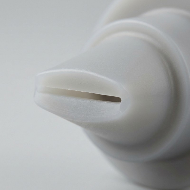
A duckbill check valve uses two flexible silicone lips that meet at the outlet. When the forward pressure reaches the required opening condition, the lips separate and create a flow passage. When the pressure difference decreases or reverses, the lips move back toward one another to resist reverse flow.
The outlet slit is therefore a functional interface, not simply a cut in the silicone. Its geometry, the contact condition between the lips and the surrounding molded profile influence how the valve opens and closes.
A slit that is too open, uneven or damaged may fail to achieve the required reverse-flow control. A slit that is difficult to separate may require more opening pressure than the application permits. Flash, local deformation and inconsistent finishing can also change the contact condition between the lips.
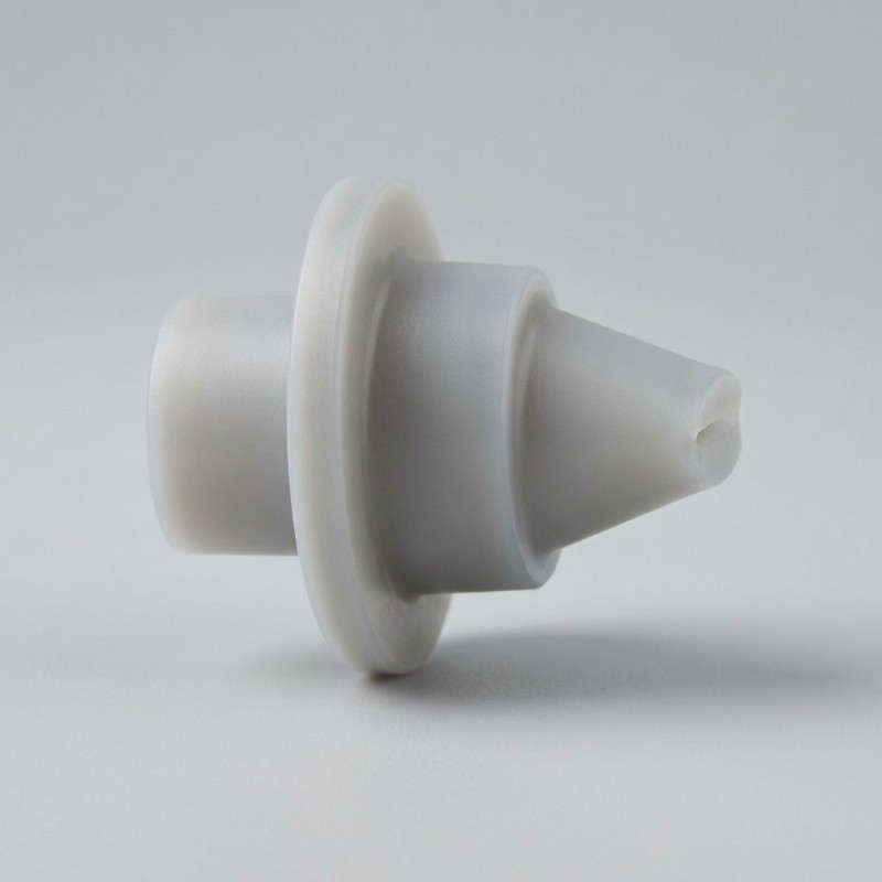
SiliconePlus lists a custom LSR silicone duckbill check valve for one-way air or fluid control. The published product description identifies a one-piece LSR body, a mounting flange, a tubular inlet and a tapered duckbill outlet.
The correct design depends on the intended working medium, pressure conditions, flow requirement, mounting housing and target acceptance criteria. No single slit shape or lip dimension should be assumed suitable for every application.
Which Valve Dimensions Must Be Defined Before Tooling?
A useful drawing should define more than the outside dimensions of the valve. The functional geometry must be documented so the mold, slit-finishing method and inspection plan can be developed around the same requirements.
The design review should cover:
- Inlet diameter: Define the inlet opening and its relationship to the mating fluid or air passage.
- Mounting flange: Specify the flange geometry, locating features and housing interface.
- Duckbill outlet profile: Show the tapered body and the intended shape of the opposing flexible lips.
- Lip thickness and transitions: Identify the critical flexible sections and transitions that influence deformation.
- Slit length and location: Define the intended outlet slit and its position relative to the lip profile.
- Material specification: Identify the proposed LSR grade and the relevant hardness or material requirements.
- Installation condition: Document how the valve is retained and supported in the mating housing.
- Functional acceptance criteria: State the required opening pressure, forward-flow behavior and allowable reverse leakage under defined test conditions.
If the design is still being developed, label undecided dimensions as engineering items for review. Do not copy dimensions from a different valve solely because the outside shape looks similar.
Design Input Review
| Design item | Information to define | Why it matters |
Inlet geometry | Opening size and mating passage | Establishes the intended inlet interface |
Mounting flange | Dimensions, location and support | Helps prevent installation-induced distortion |
Lip profile | Lip shape, thickness and transitions | Influences flexible-lip behavior |
| Slit | Length, location and finishing method | Defines the closing interface between the lips |
| Material | LSR grade and application requirements | Supports material suitability review |
| Functional criteria | Opening pressure, flow and reverse leakage | Defines how the finished valve will be evaluated |
How Do Lip Geometry and Material Affect Opening Behavior?
The opening response of a duckbill valve depends on the deformation of its flexible lips. Lip thickness, outlet profile, slit length, material properties and the support provided by the valve body work together.
Changing one feature may affect more than one functional result. For example, changing the lip profile may alter how the lips separate under forward pressure, but it can also change how they return to contact when the pressure difference reverses. A design should therefore be assessed against both forward-flow and reverse-leakage requirements.
Material hardness is another input, but it should not be used as a substitute for reviewing the geometry. Two valves made from different LSR formulations may respond differently even if their external shapes appear similar. The working medium, operating temperature and mechanical loading must also be considered when selecting the material.
The engineering review should establish the intended opening-pressure range and reverse-leakage limit before selecting the final lip dimensions. If these requirements conflict, the team may need to evaluate alternative lip profiles, material options or outlet geometry rather than adjusting one dimension in isolation.
There is no universal lip thickness, slit length or hardness that guarantees a particular opening pressure. Final values should be established through drawing-based design and validation on the finished valve.
How Should Slit Finishing and Flash Control Be Reviewed?
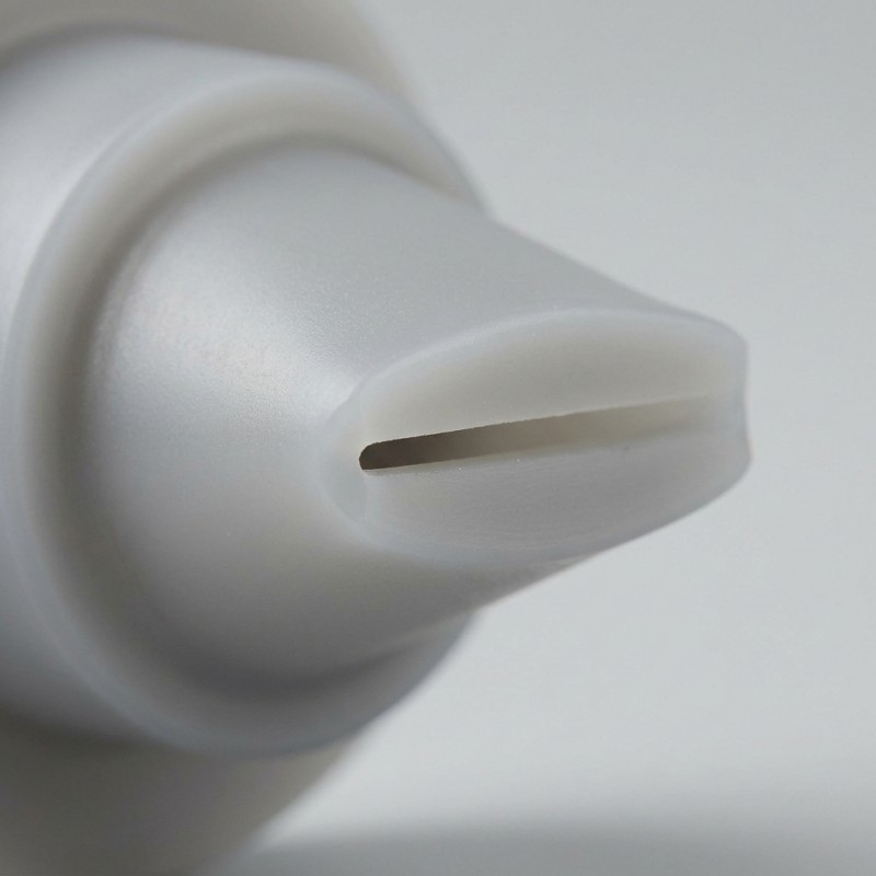
A valve can have the correct nominal dimensions and still behave inconsistently if the slit or lip contact surfaces are not finished consistently.
During DFM, the team should review how the thin lip regions will be filled, how air will be vented, where the mold parting line will sit and how the finished valve will be removed from the mold. These choices should be considered alongside the slit formation or finishing process selected for the approved design.
Flash near the lip contact surfaces deserves particular attention. Even a small unwanted projection may prevent the lips from meeting as intended. Uneven slit edges, local tearing or distortion during demolding can create a similar problem.
If the approved design requires a post-molding slit operation, that operation should be documented as part of the manufacturing process. The inspection plan should identify how the slit will be checked and how unacceptable cuts, incomplete openings or damage will be detected.
The goal is not simply to produce a visually neat part. It is to establish a repeatable process for creating the intended lip-contact condition and to confirm that the finished valve meets the agreed functional requirements.
Slit and Molding Risk Review
| Potential issue | What to review | Inspection focus |
Flash at lip edges | Parting line and shut-off arrangement | Unwanted material on the lip contact surfaces |
Incomplete filling | Thin-section flow and venting strategy | Missing material or incomplete lip formation |
Uneven slit | Slit formation and finishing method | Slit length, location and edge consistency |
| Local deformation | Demolding and handling sequence | Bent, torn or distorted lips |
| Variable lip contact | Geometry and finishing consistency | Contact condition at the closed outlet |
| Flange distortion | Mold support and installation interface | Fit in the specified mating housing |
How Should Material Compatibility and Housing Fit Be Confirmed?
The valve material and its installation environment must be considered together. Before tooling, identify the intended working medium, operating temperature, pressure conditions and any relevant chemical-compatibility requirements.
The selected LSR formulation should be reviewed for the actual application. Material suitability should not be inferred from the fact that a component is made from silicone or from its appearance in a product photograph.
Housing geometry is also important. A mounting flange that is compressed, twisted or located incorrectly during installation may change the position of the valve body or distort the flexible outlet. The drawing should show the intended support surfaces and locating features, and the assembled condition should be checked against the customer's requirements.
SiliconePlus provides liquid silicone injection molding capability for custom molded components. For this valve, the tooling review should connect material selection, flexible-lip geometry, slit finishing, flange fit and functional testing.
The silicone mold design capabilities review should be based on the real drawing and proposed manufacturing method. Any specific material, pressure, temperature or chemical-compatibility claim must be supported by the relevant project documentation and validation rather than assumed from general silicone properties.
How Should the Finished Valve Be Functionally Validated?
Validation should evaluate the finished valve rather than relying on external appearance or nominal dimensions alone. The test plan should be agreed before sample approval so the manufacturer and buyer use the same conditions and acceptance criteria.
Depending on the application, a project-specific plan may include:
- Dimensional inspection: Verify the inlet, flange, outlet profile and other drawing-defined features.
- Visual inspection: Check the lips and slit for flash, damage, incomplete formation and local deformation.
- Opening-pressure evaluation: Define the test setup and the pressure condition at which the valve is expected to begin opening.
- Forward-flow evaluation: Specify the relevant pressure or flow conditions and the acceptance criteria.
- Reverse-leakage evaluation: Define the reverse-pressure condition, test medium, duration and allowable leakage.
- Installation evaluation: Check the valve in its intended mating housing, where the housing is available.
- Conditioning or cycle testing: If required, define the operating cycles or environmental conditions and the acceptance criteria.
The test method must be appropriate to the intended application. Opening pressure measured under one test setup should not be compared directly with a result obtained using different fixtures, media, temperatures or measurement procedures.
The final report should identify the sample configuration, test conditions and acceptance criteria. SiliconePlus can support the agreed component-level inspection and sampling plan; performance of the complete system remains subject to the customer's application-specific validation.
Sample Validation Plan
| Validation item | What must be agreed | Record to retain |
Dimensions | Drawing revision and measurement method | Dimensional inspection results |
Visual condition | Lip and slit defect criteria | Visual inspection record |
Opening pressure | Test setup, procedure and acceptance range | Test conditions and measured results |
Forward flow | Test conditions and required flow behavior | Flow test record |
| Reverse leakage | Reverse-pressure condition and allowable leakage | Leakage test procedure and results |
| Housing fit | Mating part and installation condition | Assembly inspection record |
| Durability, if required | Cycle or environmental conditions | Results against defined acceptance criteria |
What Should Buyers Include in an RFQ?
A complete RFQ helps the manufacturer assess the valve geometry, tooling feasibility and validation requirements before quotation.
For a custom LSR duckbill check valve, buyers should provide:
1. 2D drawing and 3D CAD: Include the inlet, mounting flange, duckbill profile and outlet slit.
2. Application description: Identify whether the valve controls air or liquid and describe the intended system.
3. Working medium and conditions: Specify relevant temperature, pressure and chemical-compatibility requirements.
4. Functional targets: Define opening pressure, forward-flow requirements and allowable reverse leakage.
5. Material requirements: State the required LSR grade or material criteria, where already defined.
6. Mounting information: Provide the mating housing drawing and installation requirements.
7. Inspection and test plan: Identify required test methods, acceptance criteria and reporting needs.
8. Commercial information: Provide prototype needs, estimated order quantity and target schedule.
If any requirements are not yet finalized, identify them as open items for engineering review. The purpose of DFM is to identify missing information and manufacturing risks before tooling decisions are locked in.
SiliconePlus supports custom silicone manufacturing capabilities through drawing-based project review, tooling development, sampling and agreed inspection. The final quotation should be based on the actual component scope and acceptance requirements.
Frequently Asked Questions
What Does the Slit Do in a Silicone Duckbill Check Valve?
The slit is the outlet interface between the two flexible lips. It opens under the specified forward-pressure condition and allows the lips to return toward contact when the pressure difference reverses. Its geometry and finished condition influence valve behavior.
Can Slit Length Alone Determine Opening Pressure?
No. Opening behavior also depends on lip thickness, outlet profile, material properties, body geometry, installation and test conditions. Slit length should be evaluated as part of the complete valve design.
Can Flash at the Duckbill Lips Affect Reverse Leakage?
Yes. Flash or an uneven slit edge may prevent the lips from contacting as intended. The mold design, slit-finishing method and inspection plan should address these risks.
Should the Slit Be Formed During Molding or Finished Afterwards?
The appropriate method depends on the approved design and manufacturing feasibility. If a post-molding slit operation is selected, it should be included in the process documentation and inspection plan.
Does a Visually Correct Valve Guarantee the Required Flow and Leakage Performance?
No. The finished valve must be tested under agreed conditions for opening pressure, forward flow and reverse leakage where these functions are required. Appearance and dimensional inspection alone cannot establish functional performance.
Conclusion
The performance of an LSR duckbill check valve depends on the relationship between its flexible lips, outlet slit, material and installation condition. A reliable design review should define these features together rather than treating the slit as an isolated dimension.
Before tooling, confirm the valve profile, lip geometry, slit length and finishing method, material requirements, mounting interface and functional acceptance criteria. The DFM review should address thin-section filling, venting, flash control, demolding and the inspection method for the finished outlet.
Sample approval should verify both the molded geometry and the required opening, flow and reverse-leakage behavior. All numerical targets and pass/fail limits must be defined for the intended application and validated using an agreed test method.
For OEM buyers, providing complete drawings, application conditions and functional requirements early helps the manufacturer assess feasibility and prepare a more accurate quotation.
Discuss Your Custom LSR Duckbill Valve Project
Developing a custom silicone duckbill check valve for an industrial air or fluid-control assembly?
Share your 2D drawing, 3D CAD, working medium, operating conditions, mounting interface and required opening-pressure, flow and reverse-leakage criteria.
SiliconePlus can review the LSR molding feasibility, lip and slit design, tooling requirements and agreed sample validation plan.
To discuss your requirements and request a project review, contact SiliconePlus with your design information and estimated quantity.