How Should the Rigid-to-Soft Transition Be Designed in LSR Overmolded Wireless Earhook Housings?
Answer Excerpt
The rigid-to-soft transition in an LSR overmolded wireless earhook should transfer bending, handling and wearing loads gradually from the rigid plastic insert into the flexible silicone section. A reliable transition needs enough silicone thickness for molding and durability, sufficient rigid support below the soft section, a controlled termination edge and a bonding or mechanical-retention strategy matched to the real load direction.
Wireless earhook components combine two very different mechanical functions.
The rigid plastic insert provides shape, positioning and support for the internal product structure.
The overmolded LSR provides flexibility, soft touch, cushioning and a comfortable contact surface around the ear.
The highest design risk is often not located in the middle of either material.
It is located where the flexible silicone ends and the rigid insert begins.
Every time the earhook is opened, worn, removed, flexed or handled, part of the bending load can pass through this transition.
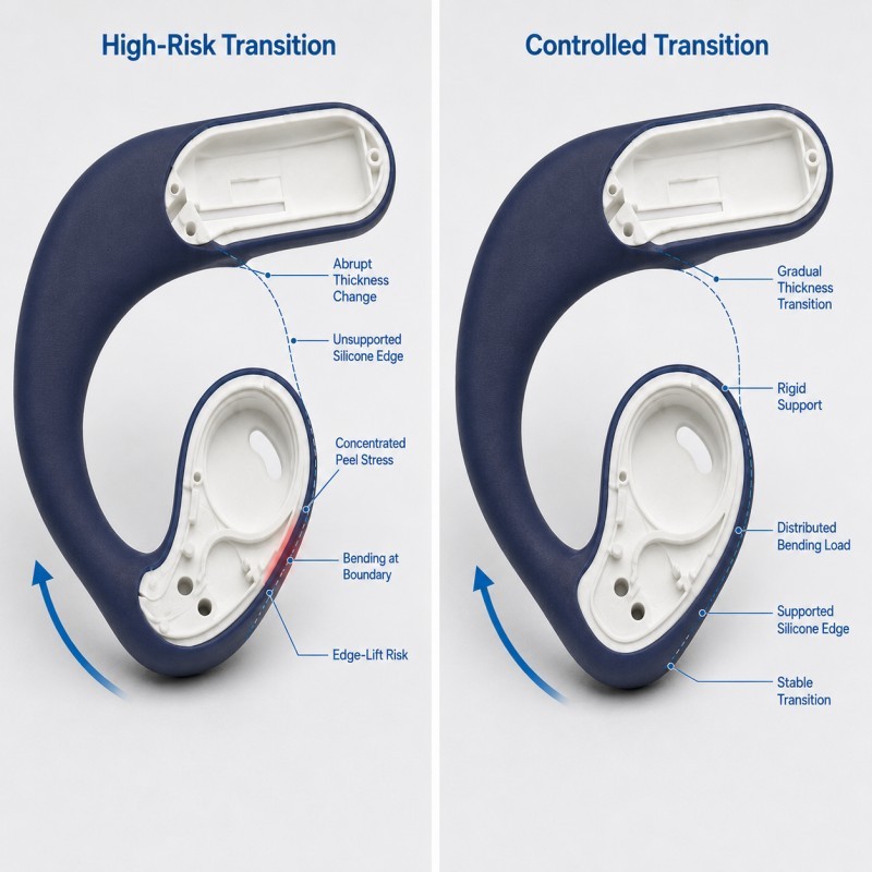
If the geometry changes too abruptly, the load may concentrate at one narrow silicone edge or bonding boundary.
This can eventually lead to edge lifting, local tearing, permanent deformation or an uncomfortable hard step.
For this reason, the silicone-to-plastic interface should be reviewed together with material compatibility, geometry and the final bending condition.
What Is the Rigid-to-Soft Transition in an Overmolded Earhook?
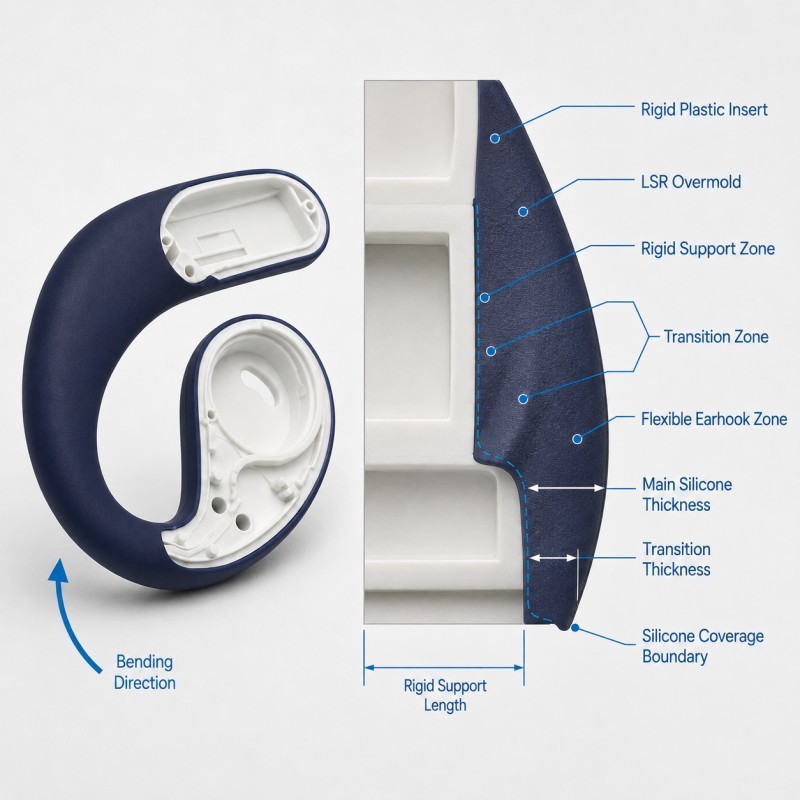
The rigid-to-soft transition is the region where the flexible LSR overmold begins or ends on the rigid earhook insert.
It is more than a cosmetic color boundary.
This region may need to transfer:
• Bending load
• Pulling load
• Torsional load
• Repeated handling force
• Local skin-contact pressure
• Assembly load
• Cleaning friction
A good transition allows these loads to move gradually between the two materials.
A high-risk transition concentrates them at one narrow edge.
Typical warning signs include:
• A very thin silicone feather edge
• An abrupt thickness step
• Insufficient plastic support
• A sharp termination corner
• The bending point located directly at the bonding edge
• A narrow bonding area
• A retention feature positioned too far from the load
The design target is not simply to make the boundary visually smooth.
The transition should remain mechanically stable after repeated use.
Why Is the Transition Area a High-Stress Region?
The rigid insert and the silicone overmold respond differently when the earhook bends.
The plastic section carries shape and structural load.
The silicone section can deform much more easily.
Where these materials meet, their different stiffness creates a change in how force travels through the component.
If the earhook repeatedly bends close to the transition, the silicone edge may experience a combination of:
• Peeling
• Shear
• Stretching
• Compression
• Twisting
This combination is more difficult to control than a simple straight pull.
For example, a silicone layer may resist a direct pulling load reasonably well but still begin lifting when repeated bending creates peel stress at one exposed edge.
The location of the normal flex zone should therefore be considered before the silicone boundary is finalized.
Where possible, the most severe bending point should not be concentrated on an unsupported termination edge.
How Should the Transition Geometry Be Designed?
A reliable transition should avoid an unnecessary sudden change from a thick flexible section to an extremely thin silicone edge.
Important geometry includes:
• Main silicone thickness
• Termination thickness
• Transition length
• Root radius
• Plastic support length
• Bonding width
• Local curvature
• Distance from the main bending zone
The silicone should remain thick enough to fill reliably and survive demolding.
At the same time, the transition should not create a bulky step that produces an uncomfortable pressure point around the ear.
A gradual thickness change can help distribute strain over a wider region.
The rigid insert should extend far enough beneath the transition to support the silicone where the boundary is most vulnerable.
The exact dimensions depend on the actual earhook geometry, silicone hardness, insert material, molding process and required flexibility.
There is no universal minimum thickness that should be copied into every wireless-earphone project.
For broader thickness guidance, review how wall thickness should be designed for LSR overmolding.
Where Should the Main Bending Zone Be Located?
The most flexible section of an earhook should be reviewed together with the rigid insert length and silicone coverage.
If the rigid insert extends too far into the flexible region, the earhook may feel too stiff.
If the rigid insert ends too early, the silicone transition may receive excessive bending load.
A useful design review should identify:
• The rigid support zone
• The controlled transition zone
• The primary flex zone
• The wearer-contact zone
These regions do not need to end at the same location.
The transition performs best when it transfers load between rigid support and flexible movement rather than becoming the only place where bending occurs.
During DFM, engineers should also review whether repeated flexing changes the outer silicone surface, creates local whitening, produces edge lifting or changes the final earhook shape.
The final flex behavior should be evaluated on the complete molded component rather than inferred from silicone hardness alone.
When Does the Earhook Transition Need Mechanical Retention?
Mechanical retention can provide an additional physical lock between the rigid insert and the silicone overmold when the transition experiences repeated peeling, pulling or bending loads.
Possible retention structures include:
• Through-holes
• Slots
• Grooves
• Undercuts
• Edge wraparound
• Retention windows
However, a retention feature should only be added when it fits the real rigid insert structure.
It should not weaken a thin plastic wall or create an unnecessary molding problem.
Important checks include:
• Distance from the transition edge
• Direction of the expected load
• Plastic wall strength
• Silicone flow path
• Venting
• Local wall thickness
• Demolding feasibility
The retention structure should resist the real failure direction.
A hole located far from the peel edge may provide less benefit than a properly supported retention feature positioned closer to the actual load path.
For detailed guidance, review when LSR overmolding needs mechanical retention.
How Does Insert Position Affect the Soft Transition?
The rigid earhook insert must remain in the correct position while LSR is injected around it.
If the insert shifts, the transition geometry may change even when the mold cavity itself is correct.
Possible results include:
• Uneven silicone thickness
• Different transition lengths
• One side becoming thinner than the other
• Uneven bonding width
• Left-right appearance variation
• Different bending behavior
• Local flash
• Reduced rigid support
This is especially important for curved earhook structures because a small insert offset can affect several sections along the curve at the same time.
The mold should locate the insert from stable rigid features and support it close to the transition region.
Inspection should verify not only the outside silicone shape but also the relationship between the internal rigid insert and the finished soft surface.
Wireless Earhook Rigid-to-Soft Transition DFM Checklist
| DFM Item | What Engineers Should Confirm | Main Risk |
Silicone coverage | Soft-touch area is clearly defined | Unnecessary overmolding |
Transition location | Boundary is away from uncontrolled flex where possible | Peel concentration |
Wall thickness | Silicone remains moldable and durable | Thin-edge tearing |
Transition length | Load changes gradually | Abrupt strain concentration |
Rigid support | Insert supports the vulnerable edge | Edge lifting |
Root geometry | Sharp stress concentration is avoided | Local cracking or tearing |
Material compatibility | Silicone and insert strategy are confirmed | Weak interface |
Retention | Mechanical lock matches real load direction | Delamination under bending |
| Insert position | Rigid core remains repeatable | Uneven soft section |
| Surface geometry | Wearer-contact transition remains smooth | Pressure point |
| Validation | Flex, peel, appearance and fit tests are defined | Sample looks good but use fails |
The silicone mold design and tooling review should confirm the rigid insert datum, silicone coverage, transition thickness, support length, mechanical-retention features, mold shut-off, gate, venting and demolding direction before mold steel is finalized.
How Should the Rigid-to-Soft Transition Be Validated?
The rigid-to-soft transition should be validated under the real bending and handling conditions expected for the earhook.
Recommended validation includes:
1. Visual Inspection
Check the silicone boundary for flash, thin edges, local lifting, surface damage and left-right variation.
2. Dimensional Inspection
Measure transition position, silicone thickness and critical earhook dimensions.
3. Flex Testing
Repeat the defined earhook bending motion and inspect the transition afterward.
4. Peel or Retention Evaluation
Where appropriate, evaluate whether the silicone can lift from the rigid insert under the expected load direction.
5. Shape Recovery Inspection
Confirm that the earhook returns to the required shape after repeated flexing.
6. Wearing-Fit Evaluation
Check whether the transition creates a hard step, local pressure point or unstable contact around the ear.
7. Environmental Conditioning
Where required, repeat inspection after the customer's defined moisture, sweat-simulation, cleaning or temperature conditions.
8. Pilot-Production Validation
Compare multiple mold cavities and consecutive molding cycles before mass-production approval.
The bending angle, cycle count, load and acceptance limits should be defined from the actual earphone design rather than copied from a generic silicone component.
How SiliconePlus Supports Wearable Earhook Overmolding DFM
SiliconePlus supports custom wearable and consumer-electronics LSR overmolding projects from insert and structural review through tooling, sampling, inspection and mass production.
Project support can include:
• Plastic insert and silicone coverage review
• Rigid-to-soft transition DFM
• Silicone wall-thickness evaluation
• Material compatibility review
• Mechanical-retention design
• Insert-positioning and support analysis
• Mold shut-off review
• Gate and venting analysis
• Precision mold development
• LSR injection molding
• Dimensional and appearance inspection
• Flex and retention test support
• Pilot-production validation
Specific transition geometry, silicone hardness, substrate material, bending range and acceptance criteria should always be confirmed according to the actual wearable product structure and customer validation requirements.
FAQ
Should the Silicone Edge Be Made as Thin as Possible?
No. An extremely thin edge may look smooth but can become difficult to fill, demold and support during repeated bending. The termination geometry should balance appearance, comfort and durability.
Should the Rigid Insert End Exactly Where the Silicone Begins?
Not necessarily. The rigid support and visible silicone boundary can be designed differently depending on the required flex behavior.
Does Softer Silicone Always Reduce Transition Stress?
No. Silicone hardness and geometry work together. A very soft but unsupported section can still deform excessively or concentrate peel load at the edge.
Does Every Earhook Need Mechanical Retention?
No. The requirement depends on material compatibility, bonding strategy, rigid insert structure and the expected bending or pulling load.
Why Can One Side of the Earhook Be Thinner Than the Other?
Possible causes include insert shift, curved-insert tolerance, uneven support or mold-loading variation.
Should the Transition Be Tested Only by Pulling the Silicone?
No. Repeated bending, fit, recovery and edge inspection can be more representative than one simple straight pull test for an earhook application.
Conclusion
A reliable rigid-to-soft transition is not created by simply reducing silicone thickness until the edge looks smooth.
The design should coordinate:
• Silicone coverage
• Transition length
• Wall thickness
• Rigid insert support
• Bending direction
• Material compatibility
• Mechanical retention
• Insert positioning
• Wearer comfort
• Flex validation
The transition should gradually transfer load from the rigid insert into the flexible earhook instead of becoming the single point where bending, peeling and twisting are concentrated.
These details should be reviewed during DFM before tooling, when the insert structure and silicone boundary can still be optimized efficiently.
Developing a Wearable Silicone-Over-Plastic Component?
If you are developing a wireless earphone, wearable device or another rigid-plastic component with a flexible LSR overmold, send your 3D drawing, substrate material, silicone coverage area, bending requirement and estimated quantity to the SiliconePlus engineering team for a project-specific DFM review.