Where Should Automotive Connectors Be Sealed? Face, Housing Perimeter and Wire Entry
Answer Excerpt
Automotive connectors may require sealing at the mating face, around a housing joint and at individual wire-entry cavities. These locations protect different potential leakage paths and should not be treated as one interchangeable gasket design.
A reliable connector sealing strategy begins by identifying where moisture could travel from the external environment toward the electrical contact region.
The main engineering questions are:
• Which connector interface is exposed to the environment?
• Where does the mating connector contact the seal?
• Is there a separate housing joint that needs protection?
• How do individual wires enter the connector body?
• Which sealing areas require axial or radial compression?
• Which plastic and metal features must remain exposed?
• Can the silicone seal be integrated through LSR overmolding?
• Would a separately molded wire seal be more suitable?
• How will the complete connector assembly be tested?
A single silicone gasket cannot automatically protect every possible entry path.
The correct sealing arrangement depends on the connector housing, wire configuration, mating structure and customer-defined environmental requirements.
What Are the Main Sealing Locations in an Automotive Connector?
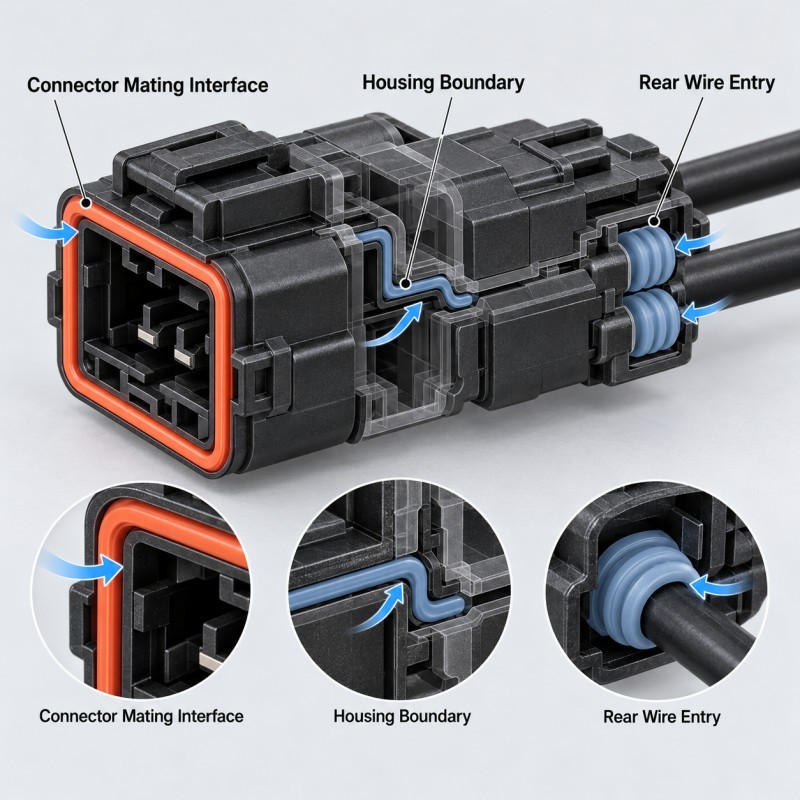
An automotive electrical connector can contain several interfaces between the protected electrical region and the surrounding environment.
Three common areas deserve separate attention.
The mating face is the interface where the connector joins its counterpart. A sealing feature may be compressed as the connectors reach their intended engaged position.
The housing perimeter is the continuous boundary around a housing interface, cover or connector body. Depending on the connector design, this perimeter may be located at the mating face or at a separate housing joint.
The wire-entry region is where individual insulated wires pass into the rear connector cavities. Moisture may travel through an inadequately sealed gap between the wire insulation and cavity wall.
These sealing positions are related, but they do not always represent three separate physical gaskets.
For example, an integrated face seal may itself form a continuous perimeter around the connector opening.
The correct number and location of seals must follow the real connector architecture.
1.Mating Face Seals: Protect the Connector-to-Connector Interface
A mating face seal provides a controlled sealing contact between a connector housing and its mating component.
For an integrated LSR design, silicone may be molded directly onto a specified area of the rigid engineering plastic housing.
A custom automotive connector interface seal can use a continuous silicone contact profile surrounding the required functional openings.
The key design requirements may include:
• Defined mating direction
• Continuous sealing path
• Correct silicone lip height
• Suitable mating-surface geometry
• Controlled final compression
• Stable plastic housing datums
• Exposed terminal cavities
• Accessible locking features
• Reliable mold shut-off boundaries
If the sealing face does not receive sufficient compression, a local leakage path may remain.
Excessive compression may increase mating force, roll the silicone lip or deform an inadequately supported housing.
The seal should therefore be reviewed with the complete connector pair, including the actual final engaged position.
The molded silicone must not obstruct terminal openings or interfere with the connector's intended locking and mating functions.
2.Housing Perimeter Seals: Follow the Actual Enclosure Boundary
A housing perimeter seal follows a continuous boundary around the area that must remain protected.
Depending on the product design, the boundary may surround a connector mating interface or a separate joint between rigid housing sections.
For a custom automotive connector peripheral seal, the molded silicone is positioned along the specified housing boundary to form a repeatable sealing contact.
Engineers should evaluate:
• The complete housing leakage boundary
• Straight sections and corners
• Seal contact width
• Local wall stiffness
• Cover or mating-part flatness
• Corner compression
• Plastic tolerance variation
• Retention of the silicone on its carrier
• Parting-line location
• Assembly support
A perimeter seal should not be designed as an isolated rubber outline.
The mating surface and the rigid housing determine whether the silicone can make continuous contact around the required path.
If the housing bends, twists or changes its assembly position, sealing compression can vary around the perimeter even when the molded silicone dimensions are correct.
It is important to distinguish the location of a housing joint from the direction in which the silicone is compressed.
A perimeter seal may operate as an axial face seal in one connector design and use a different contact arrangement in another.
3.Wire-Entry Seals: Protect Individual Cable Passages
The rear of a sealed automotive connector may contain individual wires entering separate connector cavities.
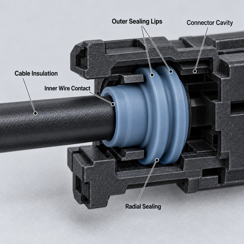
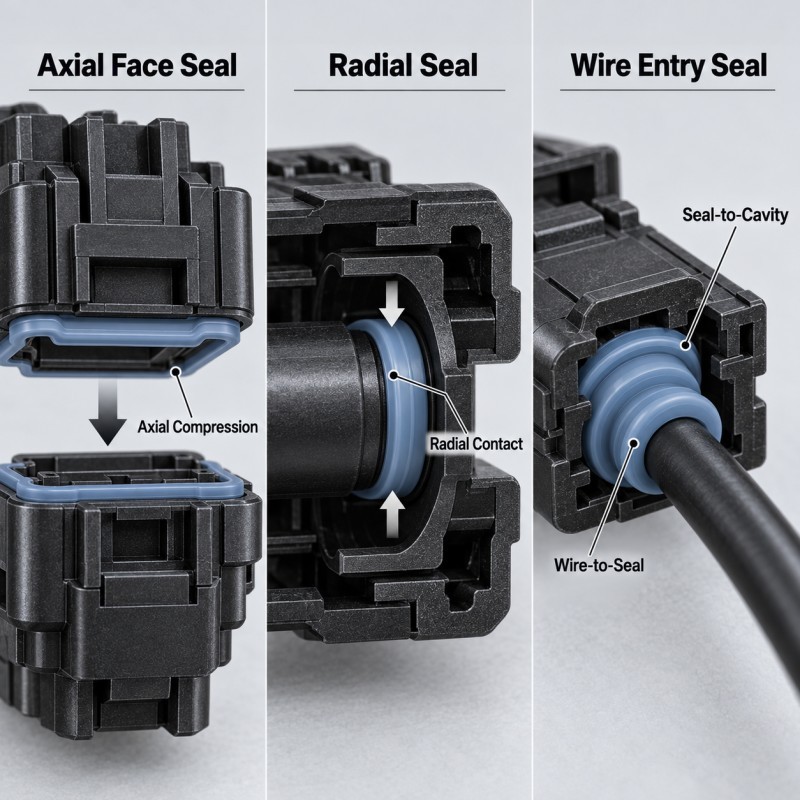
A single wire seal is commonly designed to contact both the insulation of the cable and the inner wall of the connector cavity.
A typical structure may include:
• A central wire passage
• Inner contact against the cable insulation
• External sealing lips
• A defined cavity fit
• Rounded lead-in geometry
• Controlled insertion force
• An approved silicone hardness
• Stable positioning during terminal assembly
This design is different from a large perimeter gasket.
The sealing function depends on the relationship between the wire outside diameter, seal passage, outer lip geometry and connector cavity dimensions.
For many connector systems, the single wire seal is molded separately and assembled onto the wire before terminal insertion.
It should not automatically be described as silicone permanently overmolded onto the cable.
The selected manufacturing process depends on the actual wire and connector design.
A wire seal that fits the cavity but does not seal against the cable insulation may still permit ingress.
Similarly, excessive interference may damage the seal, increase insertion force or interfere with terminal assembly.
Why Are Face Seals and Perimeter Seals Not Always Different Products?
Sealing terminology often describes more than one characteristic of a component.
The term face seal usually describes where the sealing contact occurs and how the mating surfaces approach one another.
The term perimeter seal describes the continuous path around the boundary that needs protection.
These descriptions can overlap.
An integrated silicone seal may be positioned on the mating face and follow the perimeter of the connector opening at the same time.
For this reason, an RFQ should not rely only on labels such as face seal, peripheral seal or housing gasket.
Engineers should also provide:
• The actual leakage boundary
• The mating components
• The direction of assembly
• The silicone contact surface
• The final assembly gap
• The location of rigid stops
• Required open functional regions
The correct design is defined by geometry and function, not by the product name alone.
How Should Engineers Identify the Actual Water Ingress Path?
A connector may appear sealed at the front while moisture enters through an unrelated rear cavity or housing joint.
The engineering review should trace possible paths from the exposed environment toward protected electrical areas.
These paths may include:
• A gap at the mating interface
• A discontinuity at a housing joint
• A clearance around wire insulation
• A poorly supported silicone edge
• A damaged sealing lip
• A transition between rigid and flexible materials
• An exposed opening outside the intended seal boundary
The complete connector should be reviewed in its assembled state.
A leakage path diagram can help identify which barrier controls each possible route.
If the mating face is the source of leakage, changing the wire-entry seal may not solve the problem.
If moisture enters through an individual cable cavity, increasing front-face compression may not address the actual defect.
A reliable diagnosis must identify the location of ingress before changing the silicone geometry or molding parameters.
Integrated LSR Overmolding or a Separate Silicone Seal?
Integrated overmolding and separately molded seals are both valid manufacturing approaches.
An integrated connector seal may be useful when the silicone should remain attached to a rigid plastic carrier throughout handling and assembly.
Potential advantages include:
• Repeatable seal positioning
• Reduced loose-gasket handling
• Integrated sealing geometry
• Fewer separate assembly operations
• Controlled silicone coverage boundaries
However, integrated LSR overmolding requires suitable substrate geometry, mold access, insert positioning and a validated bonding or retention strategy.
A separate molded seal may be more suitable when:
• The seal must be replaceable
• The connector uses a defined wire-seal cavity
• Standard assembly procedures require independent seals
• The gasket needs to be inspected separately
• Integrating the silicone would create unnecessary tooling complexity
The selection should consider total assembly requirements and production volume rather than assuming integrated overmolding is always the superior option.
Compression Direction and Rigid Stops Must Match the Sealing Interface
Different sealing interfaces may require different types of compression.
An axial face seal is compressed mainly along the connector closing direction.
A radial seal is compressed mainly between the surfaces of a mating cylindrical or cavity-based interface.
For a wire-entry seal, the contact geometry must be coordinated with both the wire insulation and the connector cavity.
The design should review:
• Actual compression direction
• Free seal dimensions
• Mating dimensions
• Silicone hardness
• Contact width
• Minimum and maximum tolerance conditions
• Connector insertion force
• Long-term recovery
• Rigid assembly support
Where appropriate, compression stops can establish a controlled closing position and prevent the elastomer from acting as the only mechanical limit.
However, the location and function of the stop must match the actual sealing interface.
A design that works with nominal components may still fail when minimum and maximum tolerances are combined.
The complete assembly should therefore be evaluated across the required dimensional and environmental conditions.
Protect Terminal Openings and Other Functional Areas During Molding
Automotive connectors contain functional regions that should remain free from unwanted silicone.
Depending on the connector, these may include:
• Terminal openings
• Electrical mating cavities
• Contact surfaces
• Locking features
• Mounting holes
• Locating datums
• Wire passages
• Specified inspection surfaces
For integrated seals, the molding tool must create a controlled shut-off around these regions.
Insert position, plastic tolerance, mold fit and injection conditions can all influence whether silicone stays within the approved coverage area.
Flash that extends into an electrical contact region may create more than a cosmetic issue.
It may interfere with connector mating, terminal insertion or final inspection.
These areas should have explicit dimensional and appearance acceptance requirements before tooling begins.
The objective is to form silicone only where the connector needs the selected sealing function.
How Should the Complete Connector Sealing System Be Validated?
The validation plan should distinguish individual seal inspection from complete connector performance.
Before assembly, engineers may inspect:
• Silicone seal dimensions
• Critical lip geometry
• Plastic carrier flatness
• Wire seal passage dimensions
• Silicone coverage boundaries
• Flash on functional regions
• Insert or seal positioning
• Material and batch traceability
After assembly, validation may include:
• Mating and terminal insertion checks
• Final assembly gap verification
• Compression assessment
• Air-leak or pressure-decay testing
• Water-ingress testing under the specified conditions
• Thermal cycling
• Vibration testing
• Inspection after environmental conditioning
• Pilot-production repeatability
A test result for an individual loose seal cannot establish the waterproof rating of the complete connector.
For an IP67 or IP68 target, the applicable test procedure and finished assembly requirements must be specified and verified.
The customer should determine the acceptance limits for its actual connector system.
The purpose of the test plan is to confirm that the correct sealing barriers work together, rather than assuming one successful leak test proves every interface is properly designed.
| Sealing Location | Main Interface | Typical Silicone Structure | Critical Risk | Key Validation |
Mating face | Connector-to-connector interface | Integrated LSR face seal | Insufficient mating compression | Mated connector leak test |
Housing perimeter | Continuous housing or mating boundary | Overmolded perimeter gasket | Corner gaps or housing distortion | Full-path contact and leak check |
Wire entry | Cable insulation and connector cavity | Separate multi-lip single wire seal | Wire or cavity dimensional mismatch | Wire-to-seal and cavity fit |
| Silicone-to-plastic edge | Integrated seal and rigid carrier | Bonded or mechanically retained transition | Edge lifting | Interface and environmental test |
| Functional openings | Terminal and locking areas | Controlled no-silicone zones | Flash or blocked openings | Functional inspection |
| Final assembly | Complete connector system | Combination of required seals | Unprotected leakage path | Project-specific ingress test |
What Should Buyers Include in an Automotive Connector Seal RFQ?
A connector sealing RFQ should describe the complete sealing problem rather than request only a generic waterproof silicone ring.
Useful project information includes:
• 2D connector drawing
• 3D CAD model
• Plastic housing material and grade
• Mating connector drawing
• Contact cavity geometry
• Number of wire entries
• Cable outside diameter and tolerance
• Terminal assembly information
• Intended sealing locations
• Silicone coverage boundaries
• Required assembly direction
• Compression and insertion requirements
• Environmental exposure conditions
• IP or leak-test target
• Critical inspection requirements
• Estimated production quantity
• Annual volume forecast
If the connector currently fails a leak test, the buyer should also provide the defect location, test conditions and any available failure evidence.
These details help the manufacturing team identify whether the proposed solution requires a mating face seal, a housing perimeter gasket, a wire-entry seal or more than one sealing structure.
Accurate inputs also allow tooling, sampling and production requirements to be discussed before quotation approval.
How SiliconePlus Supports Automotive Connector Sealing Projects
SiliconePlus provides custom silicone sealing and LSR overmolding manufacturing for automotive connector and wire-harness components.
Project review can include:
• Connector sealing-path evaluation
• Plastic housing and insert assessment
• Mating-face seal geometry
• Continuous housing perimeter design
• Single wire seal dimensions
• Silicone hardness selection
• Bonding or mechanical retention
• Mold shut-off and parting-line review
• Functional opening protection
• Dimensional inspection planning
• Tooling and sample development
• Pilot-production verification
Our LSR injection molding capability supports drawing-based development of precision silicone components and selected silicone-over-plastic structures.
The final manufacturing approach depends on the customer's complete connector assembly and application requirements.
SiliconePlus focuses on custom silicone components and overmolded sealing regions rather than supplying complete stocked electrical connector systems.
Frequently Asked Questions
Is a Connector Face Seal the Same as a Perimeter Seal?
Not necessarily, but the descriptions can overlap. A face seal describes the sealing contact at a mating surface, while a perimeter seal describes the path around a boundary. An integrated connector face seal may also be a perimeter seal.
Can One LSR Seal Protect Every Connector Leakage Path?
Not automatically. Different connector interfaces may require separate sealing barriers. The mating face, housing joints and wire-entry cavities should be reviewed according to the actual connector architecture.
Are Automotive Single Wire Seals Always Overmolded Onto Cables?
No. Many single wire seals are separately molded and installed onto individual wires before terminal insertion. Direct overmolding is another possible manufacturing approach, but it must be evaluated for the actual cable and connector.
Does an Integrated LSR Connector Seal Automatically Achieve IP68?
No. The achieved ingress protection depends on the complete assembled connector, including every potential leakage path, mating dimensions, wire-entry seals and the specified test conditions.
What Is the Most Important Information for a Connector Seal Quote?
The most useful inputs are the connector and mating-part drawings, sealing locations, plastic material, cable dimensions, assembly method, required leak-test conditions and expected production volume.
Conclusion
Automotive connector sealing should begin with the complete leakage-path map rather than the shape of one silicone part.
The mating face, housing perimeter and individual wire-entry cavities may require different sealing strategies.
Integrated LSR overmolding can help maintain a repeatable silicone position on a suitable rigid carrier, while separately molded single wire seals may be more appropriate for individual cable passages.
The correct design must match the actual interface, compression direction, dimensional tolerances, material combination and assembly process.
A successful sealing system is the one that protects every required leakage path and remains verifiable under the customer's real operating and test conditions.
Need a Custom Automotive Connector Sealing Solution?
If you are developing a sealed automotive connector, EV wire-harness interface or electronic housing component, send your 2D/3D drawings, plastic material, mating structure, wire dimensions, sealing locations, target test conditions and estimated production quantity to our engineering team.
You can contact SiliconePlus to review the required seal structure, LSR overmolding feasibility, tooling, sampling and custom manufacturing requirements.