Why Do LSR Overmolded Automotive Connector Seals Roll or Fold During Assembly?
Answer Excerpt
LSR overmolded automotive connector seals may roll, fold or shift during assembly when the sealing lip is too tall, too flexible, poorly supported, excessively compressed or forced across an abrupt mating edge. The problem can also appear when the rigid connector insert is off-center or the mating housing does not guide the seal uniformly. Reliable sealing requires the silicone profile, rigid support, assembly direction, mating geometry and tolerance stack-up to be designed as one system.
A connector seal can look dimensionally acceptable before assembly and still deform when the mating housing is installed.
This happens because the molded silicone profile is only one part of the sealing system.
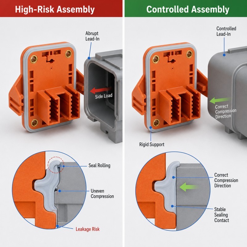
During assembly, the mating housing applies axial, radial or combined forces to the silicone.
If those forces remain aligned with the intended compression direction, the seal can deform predictably.
If the mating surface pushes the silicone sideways before the intended compression is established, the sealing lip may bend, twist or roll.
Once this happens, one section of the seal may become heavily compressed while another section loses contact.
For the broader waterproof system, review how silicone overmolded connectors should be designed for waterproof sealing.
What Does Seal Rolling Look Like During Assembly?
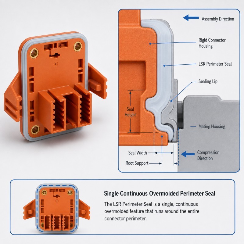
Seal rolling occurs when the silicone sealing feature is pushed sideways or rotated instead of being compressed in the intended direction.
The seal may remain attached to the connector insert, but its cross-section changes during assembly.
Typical symptoms include:
• One side of the lip folding inward
• One side rolling outward
• Silicone bunching near a housing edge
• Local twisting around a corner
• Uneven visible seal height
• Increased assembly force
• One section appearing more compressed than another
• Leakage despite apparently complete assembly
The problem may disappear when the assembly is opened because flexible silicone can partially recover.
This makes seal rolling difficult to diagnose through loose-part inspection alone.
A molded component may pass dimensional inspection while the actual failure occurs only during the mating process.
The correct inspection therefore needs to include the seal in its assembled condition.
Why Are Tall or Thin Sealing Lips More Sensitive to Rolling?
A sealing lip needs enough flexibility to conform to the mating surface, but it also needs enough structural stability to remain in the intended position.
A tall, narrow silicone feature has less lateral stability than a shorter and better-supported profile.
When the mating housing approaches from an angle or contacts the lip near its tip, the force can create a bending moment rather than direct compression.
Possible results include:
• Lip buckling
• Sideways displacement
• Folding at the root
• Uneven contact pressure
• Excessive local strain
• Difficult assembly
Increasing silicone thickness everywhere is not automatically the correct solution.
An unnecessarily thick section can increase stiffness, material use and molding time while changing the way the seal compresses.
The better approach is to evaluate sealing-lip height, width, root support and surrounding wall thickness together.
For related DFM guidance, review how wall thickness should be designed for LSR overmolding.
Why Does Rigid Support Below the Seal Matter?
The rigid connector housing should support the silicone close to the active sealing region.
When too much unsupported silicone exists below or beside the sealing lip, assembly force can move the entire soft section instead of compressing only the intended contact feature.
A well-supported structure helps control:
• Seal position
• Compression direction
• Root deformation
• Local silicone thickness
• Assembly repeatability
• Resistance to sideways loading
Support is especially important around transitions, corners and narrow connector walls.
If the underlying plastic structure is flexible or locally thin, the rigid insert itself may deform during mating.
This can create two movements at the same time:
The silicone seal deforms, and the plastic support moves.
The resulting sealing position can be very different from the nominal CAD geometry.
For this reason, connector DFM should review the stiffness and support of both materials rather than treating the silicone profile as an isolated gasket.
How Does the Mating Housing Lead-In Affect Seal Rolling?
The mating housing should guide the silicone toward its intended compressed position.
A controlled lead-in can gradually engage the seal before the final interference condition is reached.
High-risk conditions include:
• Abrupt housing edges
• Sharp entry transitions
• Insufficient lead-in
• Misaligned assembly
• Housing burrs
• Local surface steps
• Large entry interference
• An angled mating path
If the mating edge contacts the silicone suddenly, the seal may be pushed sideways.
The same seal may assemble correctly when inserted perfectly straight but roll when normal production alignment varies slightly.
This is why a sealing design should not be evaluated only using ideal CAD alignment.
The DFM review should include realistic assembly direction and allowable positional variation.
Where appropriate, the mating component may use a smoother entry transition so that the seal progressively reaches its final compression state.
How Can Excessive Compression Cause Seal Rolling or Folding?
More compression does not automatically create a better waterproof seal.
When the available mating gap becomes too small, the silicone must move somewhere.
Depending on the geometry, excessive compression can cause:
• Seal flattening
• Sideways bulging
• Lip rolling
• Local folding
• Increased assembly force
• Plastic housing distortion
• Permanent deformation
• Reduced recovery after long-term assembly
The real compression condition depends on more than the molded seal height.
It can also be affected by:
• Mating-housing dimensions
• Connector insert dimensions
• Assembly-stop position
• Housing flatness
• Mold-cavity variation
• Temperature
• Plastic deformation
Worst-case tolerance conditions should therefore be reviewed rather than approving the seal only at nominal dimensions.
Where a rigid feature limits final closing distance, review how compression stops should be designed for LSR overmolded seals.
How Does Connector Insert Offset Affect the Seal?
Even a well-designed sealing profile can become unstable if the rigid connector insert is not centered correctly.
Insert variation can include:
• Horizontal shift
• Vertical shift
• Tilt
• Rotation
• Local housing deformation
• Mold-loading variation
If the connector sits off-center, the effective mating interference may become different on opposite sides.
One side may experience excessive compression while the other side has only light contact.
The heavily compressed side is more likely to roll or fold.
The lightly compressed side may become a leakage path.
Insert positioning therefore affects both molding geometry and final assembly compression.
Locating features should use stable rigid datums, and the insert should be supported close to the silicone sealing region whenever the product structure permits it.
Mass-production validation should include realistic incoming insert variation rather than only carefully selected nominal samples.
Automotive Connector Seal Rolling DFM Checklist
| DFM Item | What Engineers Should Confirm | Main Risk |
Sealing direction | Intended compression direction is defined | Side loading |
Lip height | Profile has adequate stability | Buckling or rolling |
Lip width | Contact geometry matches real assembly | Unstable deformation |
Root support | Rigid support exists close to seal | Whole seal shifts |
Silicone hardness | Material is reviewed with geometry | Too flexible or too stiff |
Mating lead-in | Housing guides seal progressively | Abrupt edge pushes seal |
Interference | Minimum and maximum conditions are reviewed | Under- or over-compression |
Insert position | Connector remains centered | Uneven compression |
| Housing stiffness | Rigid parts do not deform excessively | Seal position changes |
| Assembly direction | Real production alignment is considered | Angled engagement |
| Validation | Assembled seal condition is inspected | Loose part passes but assembly fails |
The silicone mold design and tooling review should confirm sealing-lip geometry, rigid insert support, connector positioning, parting-line location, gate, venting and the final mating direction before mold steel is finalized.
How Should Seal Rolling Be Validated?
Seal rolling should be evaluated during and after the real assembly process rather than only through loose-part dimensional inspection.
Recommended validation includes:
1. Pre-Assembly Inspection
Confirm seal height, boundary position, insert location and visible molding quality.
2. Assembly Observation
Watch how the mating housing contacts the seal during installation and identify whether the lip is pushed sideways before compression.
3. Final Assembly Inspection
Check for visible rolling, folding, twisting or uneven seal exposure.
4. Dimensional and Gap Review
Confirm the final mating gap and relevant connector position.
5. Section or Contact Analysis
Where appropriate, inspect representative sections to understand the final compressed seal profile.
6. Assembly Force Evaluation
Monitor abnormal increases or variation in assembly force when required by the project.
7. Leak Testing
Complete the agreed air-leak, pressure-decay, immersion or other waterproof test on the final assembly.
8. Minimum and Maximum Tolerance Validation
Evaluate representative worst-case dimensional conditions rather than nominal parts only.
9. Thermal and Mechanical Validation
Where required, repeat sealing evaluation after the defined temperature, vibration or mechanical conditions.
10. Pilot-Production Review
Compare multiple mold cavities and consecutive production cycles before mass-production approval.
How SiliconePlus Supports Connector Seal DFM
SiliconePlus supports custom connector and precision LSR overmolding projects from drawing and assembly review through tooling, sampling, inspection and mass production.
Project support can include:
• Connector and mating-housing DFM
• Silicone sealing-profile review
• Wall-thickness and hardness evaluation
• Rigid insert support analysis
• Insert-positioning design
• Compression and tolerance review
• Mating lead-in review
• Mold shut-off and parting-line analysis
• Gate and venting review
• Precision mold development
• LSR injection molding
• Dimensional and appearance inspection
• Assembly and waterproof test support
• Pilot-production validation
Specific seal geometry, silicone hardness, interference, mating structure and waterproof acceptance criteria should always be confirmed according to the actual connector assembly and customer test method.
FAQ
Does a Rolled Seal Always Leak?
Not necessarily, but rolling changes the intended sealing geometry and makes contact pressure less predictable. The final assembly should be validated using the required leak test.
Is Softer Silicone Less Likely to Roll?
Not always. Softer silicone can conform easily, but a tall or poorly supported soft lip may also bend or roll more easily under side loading.
Can Increasing Seal Thickness Prevent Rolling?
Not automatically. Thickness, height, width, root support, hardness and mating geometry should be evaluated together.
Why Does Only One Side of the Connector Seal Roll?
Possible causes include connector offset, housing misalignment, uneven interference, local support differences or an angled mating path.
Can More Assembly Force Push the Seal Back Into Position?
Additional force may actually increase rolling or over-compression. The root cause should be corrected through geometry, alignment and tolerance control.
Should Seal Rolling Be Checked Before or After Waterproof Testing?
Both. Assembly inspection helps identify the deformation mechanism, while the final waterproof test confirms whether the assembled sealing path remains functional.
Conclusion
LSR seal rolling is not simply a silicone-material problem.
Reliable automotive connector sealing requires coordinated control of:
• Sealing-lip geometry
• Silicone hardness
• Rigid support
• Mating lead-in
• Assembly direction
• Compression
• Connector positioning
• Housing tolerance
• Final assembly condition
• Waterproof validation
The seal should be guided into its intended compressed position rather than pushed sideways during mating.
The best time to identify rolling risk is during DFM, before the mold and mating connector geometry become difficult to change.
Need a DFM Review for an Overmolded Connector Seal?
If you are developing an automotive or electronic connector with an integrated LSR sealing structure, send your connector drawing, mating-housing drawing, silicone coverage area, assembly direction and waterproof test requirements to the SiliconePlus engineering team for a project-specific DFM review.