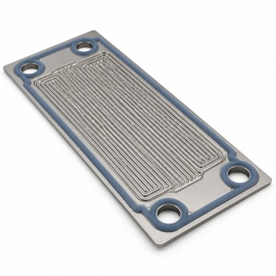
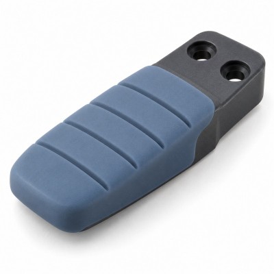
Why Do LSR Overmolded Parts Tear, Stretch, or Deform During Demolding?
Introduction
An LSR overmolded component may leave the mold with a complete shape but still contain damage created during part removal.
The silicone may be:
- Torn around a sealing lip
- Stretched near an undercut
- Distorted around a hole
- Twisted around a plastic insert
- Lifted from a metal edge
- Whitened near an FPC transition
- Permanently elongated
- Deformed around a connector opening
- Damaged at a thin membrane
- Pulled away from a bonding boundary
Some defects are visible immediately.
Others appear only after the part has cooled, returned to its natural shape, been assembled, bent, waterproof-tested, or compared with an approved reference sample.
Liquid silicone rubber is flexible, but flexibility does not mean that every geometry can be removed from a mold without controlled strain.
LSR is normally metered as a two-component material, injected into a heated mold and cured into an elastomeric component. The finished part must then be separated from the mold without exceeding the limits of its thin sections, bonding interface, insert geometry or cured mechanical properties.
For engineers, quality teams and OEM buyers, the key question is not only:
“Can the part be removed from the mold?”
The more important question is:
“Can every cavity produce parts that are removed repeatedly without tearing, stretching, whitening, distortion or hidden damage?”
This guide explains how product geometry, mold design, curing, material selection, insert structure, removal method and post-demolding handling affect stable demolding in precision liquid silicone injection molding.
Answer Excerpt
LSR overmolded parts may tear, stretch or deform during demolding when the cured silicone must pass over deep undercuts, sharp edges, small openings, negative draft, thin sealing lips or rigid insert features.
The risk increases when the silicone is insufficiently cured, excessively hot, locally thin, difficult to release from the mold surface, pulled in the wrong direction or unsupported during removal.
Plastic, metal, FPC and cable inserts can create additional stress because the insert remains rigid while the surrounding silicone stretches.
Reliable demolding requires the product geometry, draft, undercut, wall thickness, edge radius, material properties, curing conditions, mold finish, release strategy, removal direction, robot or manual handling and cooling method to be evaluated as one complete manufacturing system.
1. What Is an LSR Demolding Defect?
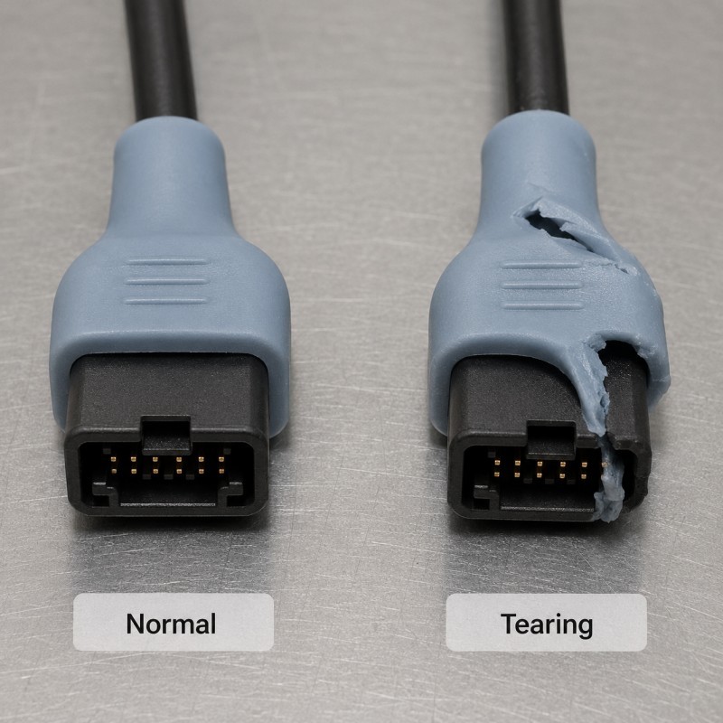
An LSR demolding defect is damage or dimensional change created while the cured silicone component is being separated from the mold.
Common defects include:
- Complete tearing
- Small edge cracks
- Stretched holes
- Elongated sealing lips
- Permanent deformation
- Product twisting
- Oval openings
- Insert displacement
- Local delamination
- Stress whitening
- Surface abrasion
- Folded membranes
- Rolled edges
- Damaged bristles or ribs
- Slow dimensional recovery
The defect may occur during:
- Mold opening
- Core withdrawal
- Ejection
- Manual pulling
- Robot removal
- Product separation from a runner
- Removal from a fixture
- Placement into a cooling tray
- Secondary trimming
The first investigation should identify exactly when the damage appears.
A part damaged during mold opening requires a different corrective action from a part distorted after being placed while still hot.
2. Flexible Silicone Still Has Structural Limits
Cured silicone can stretch, bend and recover, but its behavior depends on:
- Material grade
- Shore A hardness
- Tear strength
- Elongation
- Wall thickness
- Product temperature
- Strain direction
- Edge condition
- Number of repeated cycles
- Local stress concentration
A thick silicone handle may pass over a moderate undercut without damage.
A thin sealing membrane made from the same material may tear under much lower removal force.
The design should therefore not rely on material flexibility alone.
Engineers should calculate or evaluate where the silicone must stretch during removal and whether the weakest area can withstand that strain repeatedly.
The most vulnerable section—not the thickest section—often determines whether the product can be demolded reliably.
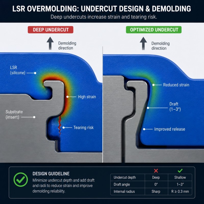
3. Deep Undercuts Increase Removal Strain
An undercut is a feature that mechanically prevents the part from moving directly out of the mold.
Examples include:
- Internal grooves
- Wraparound lips
- Retention rings
- Mushroom features
- Reverse hooks
- Deep holes
- Recessed sealing structures
- Mechanical-locking features
- Overmolded flanges
- Narrow-neck openings
To remove the product, the silicone may need to stretch over the undercut and then recover.
Demolding risk increases with:
- Greater undercut depth
- Smaller opening diameter
- Thicker rigid insert
- Shorter stretch length
- Sharper feature edges
- Higher removal speed
- Lower available flexibility
- More complex removal direction
The current SiliconePlus DFM guide also identifies deep undercuts, negative angles, thin lips and weak silicone bridges as structures requiring early demolding review.
An undercut may be possible in one engineering sample but still unsuitable for stable multi-cavity mass production.
Demolding direction, draft, undercuts and weak silicone sections should therefore be reviewed during the DFM process before final tooling.
4. Negative Draft Can Lock the Part Inside the Mold
Draft helps a molded component separate from the cavity.
A negative draft creates a geometry that becomes wider or more mechanically locked in the removal direction.
High-risk areas include:
- Deep vertical walls
- Internal sealing grooves
- Connector cavities
- Blind holes
- Thin sleeves
- Long tubes
- Wraparound edges
- Textured sidewalls
When draft is insufficient, the part may experience:
- High surface friction
- Sudden release
- Edge rolling
- Wall stretching
- Surface abrasion
- Permanent elongation
- Manual demolding variation
Silicone flexibility may allow the part to be pulled out, but repeated forced removal can still damage the product or slow the production cycle.
Draft should be reviewed according to the actual mold surface, depth, material, wall thickness and removal method.
5. Thin Sealing Lips Are Especially Vulnerable
Thin sealing lips are widely used in:
- Waterproof connectors
- Electronic housings
- Sensor seals
- Medical components
- Wearable devices
- Button structures
- Automotive interfaces
- Cable entries
These lips may need to be thin enough to compress during assembly, but they must also survive molding and demolding.
Possible demolding defects include:
- Lip tearing
- Lip stretching
- Rolled edges
- Permanent bending
- Uneven height
- Local whitening
- Damage near the parting line
SiliconePlus’s current waterproof overmolding guide notes that excessively thin silicone areas can cause incomplete filling, tearing during demolding, weak bonding and deformation after assembly.
The sealing lip should therefore be reviewed for both final sealing performance and manufacturing removal.
A lip that seals well in CAD but cannot be removed consistently is not a production-ready design.
6. Thin Membranes Can Fold or Stretch During Removal
Thin membranes may be used for:
- Pressure equalization
- Waterproof barriers
- Flexible buttons
- Sensor protection
- Medical valves
- Acoustic interfaces
- Switch structures
- Dust protection
During demolding, a membrane can:
- Fold onto itself
- Stick to a core
- Stretch in one direction
- Become concave
- Tear near its perimeter
- Remain inverted
- Develop uneven thickness
Membrane performance depends on:
- Diameter
- Thickness
- Edge radius
- Supporting frame
- Core surface
- Vacuum release
- Curing condition
- Removal direction
- Product temperature
A membrane should not be pulled through a small opening without confirming the required deformation.
Where possible, the mold should release the membrane with controlled support rather than relying on an operator to unfold it afterward.
7. Abrupt Thickness Transitions Concentrate Stress
A thick silicone section can resist pulling while an adjacent thin section stretches excessively.
High-risk transitions include:
- Thick base connected to a thin lip
- Thick strain relief connected to a membrane
- Thick overmold around a narrow edge
- Thick button body connected to a thin hinge
- Thick cable seal connected to a thin sleeve
- Thick mechanical lock connected to a narrow bridge
During demolding, force travels through the structure.
If the transition is abrupt, the strain may concentrate in one narrow area.
Possible results include:
- Whitening
- Small tears
- Necking
- Permanent elongation
- Local delamination
- Dimensional drift
Gradual wall-thickness transitions and suitable radii can distribute the removal load over a wider area.
Changing material hardness alone cannot fully correct a geometric stress concentration.
8. Sharp Mold or Insert Edges Can Cut the Silicone
A sharp edge can act like a cutting point during demolding.
The edge may belong to:
- A plastic insert
- A stamped metal terminal
- A metal housing
- A core pin
- A mold shutoff
- An FPC stiffener
- A connector opening
- A mechanical-locking hole
When the silicone stretches over the edge, the local strain becomes concentrated.
Possible defects include:
- Edge cuts
- Internal tears
- White stress lines
- Surface scratches
- Bonding-edge lifting
- Damage that grows during later bending
The external product may appear smooth even when a sharp insert edge is hidden underneath the silicone.
DFM review should therefore inspect the full substrate geometry, including hidden corners, burrs, stamped edges and hole entrances.

9. Insufficient Curing Can Cause Tearing or Permanent Stretch
A part may look fully filled but still lack sufficient cured strength when the mold opens.
Possible causes include:
- Curing time too short
- Mold temperature too low
- Uneven mold temperature
- Incorrect A/B ratio
- Unstable material mixing
- Excessive local thickness
- Cold insert absorbing heat
- Catalyst inhibition
- Production cycle variation
An under-cured part may:
- Feel unusually soft
- Stretch during removal
- Remain tacky
- Tear at thin areas
- Deform permanently
- Separate from the insert
- Produce inconsistent dimensions
Increasing removal force does not solve insufficient curing.
The curing condition must provide enough mechanical integrity for demolding while still meeting cycle-time and insert-temperature requirements.
10. Excessive Curing Can Also Create Problems
Longer curing is not always the correct solution.
Depending on the material and product, excessive heat exposure may contribute to:
- Reduced production efficiency
- Plastic-insert deformation
- Greater adhesion to certain mold surfaces
- Difficult release
- Higher product temperature at removal
- Increased stress during cooling
- Color or surface variation
A longer cycle may make the silicone stronger, but it may also expose sensitive plastic, FPC, adhesive, coating or electronic inserts to unnecessary heat.
The correct process should balance:
- Complete curing
- Demolding strength
- Bonding requirement
- Insert stability
- Product temperature
- Cycle time
- Dimensional consistency
The curing window should be established using the final material and actual insert.
11. Demolding Temperature Changes Product Behavior
The part is normally removed while it is still warm.
At a higher temperature, the silicone may be:
- Softer
- Easier to stretch
- More vulnerable to temporary deformation
- Slower to recover
- More sensitive around thin areas
At a lower removal temperature, the part may:
- Hold its geometry better
- Require a longer cycle
- Adhere more strongly to some mold surfaces
- Become more difficult to release from deep features
The appropriate demolding temperature depends on:
- Silicone grade
- Hardness
- Product size
- Wall thickness
- Undercut
- Insert material
- Mold surface
- Removal speed
The product should be measured after a defined cooling or conditioning period rather than immediately after hot removal.
12. Material Hardness Does Not Alone Determine Demolding Success
A softer silicone may stretch more easily over an undercut.
However, it may also:
- Elongate excessively
- Recover slowly
- Fold during removal
- Deform around an insert
- Produce unstable dimensions
A harder silicone may provide:
- Greater shape support
- Faster dimensional recovery
- More stable handling
But it may also:
- Require greater removal force
- Concentrate stress at thin sections
- Tear around sharp undercuts
- Be less forgiving around negative draft
Material selection should consider:
- Tear strength
- Elongation
- Hardness
- Recovery
- Compression properties
- Bonding system
- Final use conditions
Two materials with the same Shore A hardness may still show different demolding behavior because their formulations and tear properties differ.
13. Mold Surface Finish Affects Friction and Release
The mold surface directly contacts the cured silicone.
Surface conditions may include:
- High polish
- Fine matte texture
- Coarse texture
- EDM finish
- Laser texture
- Machining marks
- Scratches
- Residue
- Local repair areas
A smooth polished surface may reduce friction in some structures.
A deep texture may increase the mechanical contact area and require more stretching during release.
Damaged or contaminated surfaces can cause:
- Drag marks
- Surface abrasion
- High removal force
- Local sticking
- Product tearing
- Texture distortion
Surface finish should be selected according to both product appearance and demolding feasibility.
A cosmetic texture should not be approved without confirming that it can release consistently from the actual geometry.
14. Mold-Release Agent Must Be Controlled
Release agents may assist difficult demolding in suitable processes, but they should not become a substitute for correct mold design.
Too much release agent can:
- Create mold deposits
- Cause surface variation
- Affect appearance
- Contaminate the bonding interface
- Interfere with downstream processes
- Require frequent cleaning
- Produce inconsistent results
WACKER’s processing guidance states that release agents can support demolding, but excessive use can form deposits on hot mold walls and create inhomogeneity in the product.
For overmolded parts, the release strategy must also consider:
- Silicone-to-plastic bonding
- Silicone-to-metal bonding
- FPC encapsulation
- Medical or skin-contact requirements
- Painting or printing
- Cleaning standards
The project should use only a validated release method that matches the material and product requirements.
15. Vacuum Can Hold the Part to the Core
A closed surface may remain attached to a core because air cannot enter quickly during removal.
This can occur with:
- Deep cups
- Blind cavities
- Long sleeves
- Suction-like structures
- Closed membranes
- Large flat surfaces
- Internal tubes
Possible symptoms include:
- Sudden release
- Product inversion
- Wall stretching
- Core marks
- Permanent deformation
- Manual operators using excessive pulling force
The mold may require:
- Air-release paths
- Controlled venting
- Core movement
- Ejection support
- Surface adjustment
- A different removal sequence
A product that remains attached because of vacuum should not be corrected only through stronger robot pulling.
16. Plastic Inserts Can Move During Demolding
In silicone over plastic projects, the silicone may grip the mold and transfer removal force into the plastic substrate.
Possible results include:
- Plastic insert shifting
- Thin housing deformation
- Silicone edge lifting
- Bonding damage
- Hole distortion
- Insert cracking
- Assembly dimensions changing
The risk is higher when:
- The plastic wall is thin
- The insert has limited support
- The silicone wraps around the insert
- The bonding area is narrow
- The plastic softens at mold temperature
- Removal force is uneven
The plastic insert should remain supported until the silicone has cleared the critical mold features.
The removal method should not use the plastic’s weakest area as the main pulling point.
17. Metal Inserts Can Create Hidden Tear Points
Silicone over metal projects require the insert edge, burr level, hole entrance and demolding direction to be reviewed together.
Metal inserts are generally rigid, but they may contain:
- Sharp stamped edges
- Burrs
- Threads
- Holes
- Slots
- Plating steps
- Thin terminals
- Corners
Silicone may stretch over these features during removal.
A small burr may not be visible after molding, but it can cut the silicone from inside.
Silicone over metal projects should therefore control:
- Edge radius
- Burr level
- Insert orientation
- Surface cleanliness
- Hole entrance
- Metal flatness
- Fixture position
- Removal direction
The metal insert and silicone mold must be treated as one combined geometry.
18. FPC and Cable Exits Need Controlled Strain Relief
FPC silicone overmolding and cable projects create flexible transition areas that require controlled support during demolding.
During demolding, an operator or robot may unintentionally pull the product by:
- The cable
- The FPC tail
- A connector
- A narrow strain-relief section
- An exposed terminal area
This can transfer removal force directly into:
- Silicone bonding edges
- Copper traces
- FPC stiffeners
- Cable insulation
- Solder joints
- Thin overmolded transitions
FPC silicone overmolding requires a removal method that supports the overmolded body while protecting exposed circuit and bending areas.
The FPC tail should not become the default handle for pulling the component out of the mold.
19. Stress Whitening Can Be an Early Warning Sign
A part may not tear completely but may turn white, cloudy or glossy around a highly strained area.
This condition should be evaluated together with the causes of silicone whitening after bending, stretching, demolding or assembly.
Possible locations include:
- Undercuts
- Sharp insert edges
- Holes
- Thin lips
- Cable exits
- Mechanical-locking features
- FPC transitions
Stress whitening can indicate that the silicone structure experienced concentrated deformation during removal.
The current SiliconePlus whitening guide explains that bending, stretching, demolding and assembly can produce white or cloudy areas when strain becomes concentrated.
A white line should be evaluated for:
- Recovery after conditioning
- Surface damage
- Internal tearing
- Bonding integrity
- Dimensional change
- Growth during repeated bending
A part that looks acceptable after the white mark fades may still require structural review.
20. Parting-Line Flash Can Tear During Removal
Flash around a parting line may remain attached to both the product and the mold.
During demolding, it can:
- Pull on a sealing lip
- Tear a thin edge
- Leave a rough surface
- Create a notch
- Damage a hole
- Remain partially attached
- Affect automatic removal
Flash-related demolding risk depends on:
- Mold shutoff accuracy
- Insert tolerance
- Parting-line location
- Vent dimensions
- Injection pressure
- Mold wear
- Clamping stability
Critical edges should be reviewed together with flash and tolerance control.
A thin flash membrane may look minor but can act as a tearing path during high-speed production.
21. Robot Removal Must Match the Product Geometry
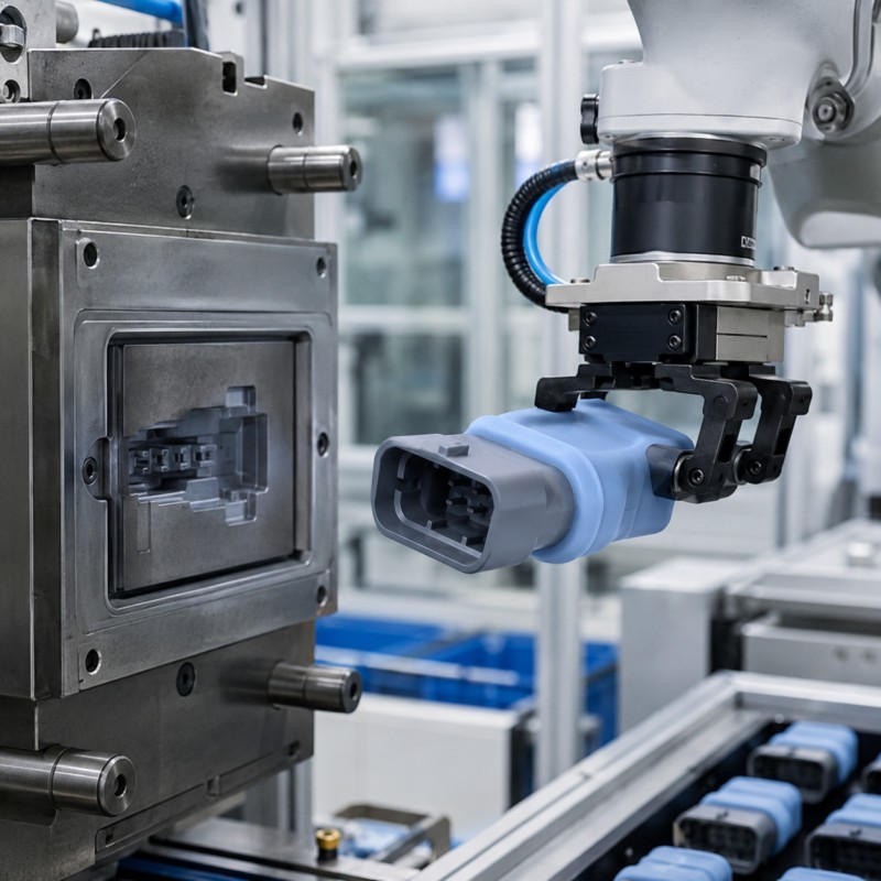
Automated removal can improve consistency, but only when the robot and end-of-arm tooling are designed for the component.
Important variables include:
- Gripping location
- Gripping force
- Pull direction
- Pull speed
- Product support
- Number of grip points
- Core-release sequence
- Product temperature
- Placement orientation
A robot that pulls too quickly may:
- Stretch thin areas
- Tear undercuts
- Shift inserts
- Distort openings
- Produce repeated cavity-specific damage
A robot that grips too softly may drop or twist the part.
Removal parameters should be treated as controlled process settings, not only as automation programming.
22. Manual Demolding Can Create Operator Variation
Manual removal may be appropriate for complex samples or lower-volume components.
However, different operators may:
- Pull from different locations
- Use different force
- Twist the product differently
- Release one side first
- Correct distorted parts manually
- Place hot parts in different orientations
This variation can create inconsistent:
- Dimensions
- Appearance
- Recovery time
- Tear rate
- Cycle time
- Cavity performance
The work instruction should define:
- Where to grip the product
- Which side to release first
- The required removal direction
- Areas that must not be pulled
- How the insert should be supported
- How the product should be placed after removal
- Which defects require rejection
Operator training should use actual reference samples and clear photographs.
23. Hot Parts Need Controlled Cooling and Placement
A product can leave the mold without damage but deform afterward.
Possible causes include:
- Stacking hot parts
- Placing products on an uneven surface
- Allowing heavy inserts to bend the silicone
- Folding thin lips
- Compressing parts in a tray
- Hanging cables without support
- Packing before dimensional recovery
Hot-part handling may affect:
- Flatness
- Roundness
- Seal height
- Insert position
- Hole dimensions
- Surface marks
- Bonding-edge stress
Cooling fixtures or dedicated trays may be required for components that cannot support their own weight immediately after demolding.
Inspection timing should be defined after the expected recovery period.
24. Why Can Samples Demold Correctly but Mass Production Fails?
Engineering samples are normally produced under close supervision.
During sampling:
- Mold surfaces are clean
- Removal speed is reduced
- Inserts are selected carefully
- Engineers release each undercut manually
- Products are placed individually
- Production runs are short
Mass production introduces:
- Longer continuous runs
- Multiple cavities
- Mold-surface deposits
- Tool wear
- Faster robot movement
- Operator changes
- Insert-batch variation
- Mold-temperature drift
- Flash buildup
- Hot-part stacking
- Shortened cycle time
A design with little demolding margin may pass twenty samples but begin tearing after thousands of cycles.
Pilot production should evaluate:
- Every cavity
- Beginning and end of the run
- Continuous-cycle stability
- Demolding force
- Tear location
- Stress whitening
- Product dimensions after recovery
- Robot or operator consistency
- Mold-cleaning intervals
25. A Practical Demolding-Failure Analysis
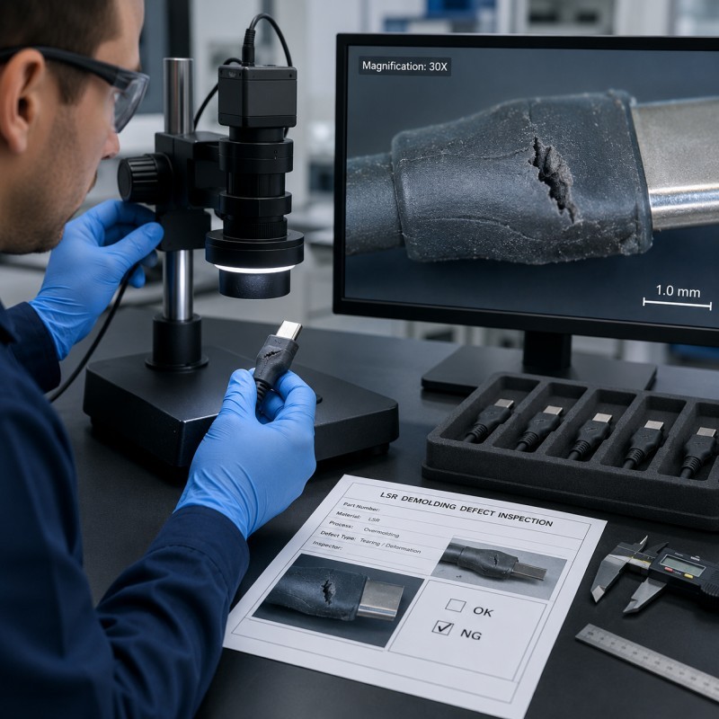
When LSR overmolded parts tear or deform during removal, investigate the problem systematically.
Recommended sequence:
- Identify the exact defect location.
- Record when the defect first becomes visible.
- Confirm the mold-cavity number.
- Compare passing and failing samples.
- Observe the complete removal process.
- Record the gripping location and removal direction.
- Check whether the product is sticking to the cavity or core.
- Review all undercuts and negative draft.
- Measure thin lips, membranes and bridges.
- Inspect insert edges, burrs and hidden corners.
- Check the mold surface for scratches or deposits.
- Review curing time and mold temperature.
- Confirm material grade and hardness.
- Inspect parting-line flash.
- Review robot speed or operator method.
- Check product temperature at removal.
- Review cooling and placement.
- Compare dimensions after a defined recovery period.
- Change one controlled variable.
- Repeat production and document the result.
Do not change material, cure time, mold surface, release agent and robot speed simultaneously.
Changing one controlled variable at a time makes the root cause easier to confirm.
26. What Should Be Validated Before Mass Production?
Before approving an LSR overmolded component, buyers and manufacturers should confirm:
- Final silicone material
- Shore A hardness
- Tear and elongation requirements
- Substrate material
- Insert edge condition
- Demolding direction
- Draft
- Undercut depth
- Opening dimensions
- Thin-wall dimensions
- Sealing-lip thickness
- Membrane thickness
- Wall-thickness transitions
- Edge radius
- Mold surface finish
- Texture depth
- Parting-line location
- Flash standard
- Curing process window
- Product temperature at removal
- Release-agent policy
- Core-release sequence
- Robot or manual removal
- Gripping location
- Removal speed
- Cooling support
- Conditioning time
- Dimensional inspection timing
- Cavity traceability
- Pilot-production quantity
- Reference samples
- Mold-maintenance plan
Approval should not be based only on whether the product can be removed once.
The process should demonstrate repeatable demolding without tearing, permanent stretch, whitening, insert movement or dimensional instability.
How SiliconePlus Supports Stable LSR Demolding
SiliconePlus provides custom liquid silicone injection molding and silicone overmolding services for precision components used in automotive electronics, 3C electronics, sensors, medical devices, wearable products, beauty devices and industrial equipment.
Our project support can include:
- DFM and drawing review
- Demolding-direction evaluation
- Undercut and draft review
- Thin-wall and sealing-lip review
- Insert-edge evaluation
- Silicone material and hardness selection
- Silicone over plastic
- Silicone over metal
- FPC silicone overmolding
- Custom mold development
- Mold-surface and texture review
- Curing-process optimization
- Robot or manual removal planning
- Sample and pilot production
- Appearance and dimensional inspection
- Stress-whitening inspection
- Functional and waterproof-test coordination
- OEM/ODM mass production
SiliconePlus’s current capabilities cover liquid silicone molding and silicone overmolding with plastic, metal and FPC substrates, supported by custom mold and production-process planning.
With 25+ years of silicone manufacturing experience, our team evaluates whether the component can be molded, bonded, demolded, inspected and produced consistently—not only whether the first sample can be removed manually.
The objective is to establish a stable demolding process that protects:
- Thin sealing structures
- Insert positioning
- Bonding boundaries
- Functional openings
- FPC and cable transitions
- Cosmetic surfaces
- Final dimensions
What Information Should Buyers Send for Evaluation?
To evaluate an LSR demolding problem, buyers should provide:
- 2D drawing
- 3D file
- Product photographs
- Defect close-up photographs
- Demolding video
- Substrate material
- Insert drawing
- Silicone material
- Silicone hardness
- Thin-wall dimensions
- Undercut dimensions
- Sealing-lip dimensions
- Current demolding direction
- Mold-cavity number
- Mold temperature
- Curing time
- Robot or manual removal method
- Defect location
- Affected quantity
- Measurement report
- Waterproof or functional requirements
- Estimated future order quantity
When possible, provide passing and failing parts from different mold cavities and production periods.
Frequently Asked Questions
Why does an LSR part tear only during demolding?
The cured part may be forced over an undercut, sharp edge, narrow opening or negative draft that concentrates strain beyond what the local silicone section can withstand.
Does softer silicone always make demolding easier?
No. Softer silicone may stretch over undercuts more easily, but it can also elongate excessively, deform, fold or recover slowly. Material and geometry must be evaluated together.
Can longer curing prevent tearing?
Longer curing may improve demolding strength when the part is under-cured, but excessive heat or time can affect inserts, cycle time and product behavior. The complete process window should be validated.
Can mold-release agent solve a sticking problem?
A validated release agent may help in some processes, but excessive use can cause deposits and surface inconsistency. Mold geometry, finish, curing and bonding requirements should be reviewed first.
Why does the part turn white but not tear?
Whitening may indicate concentrated stretching or internal stress. The area should be checked for recovery, cracks, dimensional change and later fatigue.
Why does one mold cavity tear more than another?
Possible causes include cavity-surface differences, venting, temperature variation, flash, core dimensions, insert position, tool wear or different removal paths.
Can a robot remove complex undercuts?
Yes, when the mold release sequence, gripping point, product support, pull direction, speed and product geometry are designed for automated removal.
Can the mold be modified to improve demolding?
Possible modifications include changing draft, polishing the surface, adjusting an undercut, replacing a core, increasing edge radius or changing the parting structure. Feasibility depends on the completed mold and product requirements.
Should parts be measured immediately after demolding?
Precision inspection should use a defined cooling or conditioning period because hot silicone may still recover after removal.
What should be approved before bulk production?
Buyers should approve material, geometry, undercuts, thin sections, mold finish, curing, removal method, cooling support, appearance, dimensions, cavity consistency and pilot-production results.
Conclusion
LSR demolding defects are rarely caused by one machine setting.
Tearing, stretching, whitening and deformation may result from deep undercuts, negative draft, thin sealing lips, sharp insert edges, abrupt wall-thickness transitions, incomplete curing, mold-surface friction, vacuum, flash, uncontrolled pulling or incorrect hot-part handling.
Although cured silicone is flexible, every structure has a practical strain limit.
The most reliable approach is to review demolding direction before tooling, reduce unnecessary stress concentrations, validate the final material and curing process, control the mold surface and removal method, and confirm stability through pilot production.
If you are developing an LSR overmolded connector, FPC component, cable assembly, sensor, metal insert, plastic housing or waterproof seal with tearing or deformation problems, contact SiliconePlus and send us your drawings, substrate information, silicone requirement, demolding video, defect photographs, critical dimensions, test standards and estimated quantity. Our engineering team will review the project and provide practical manufacturing recommendations.