Why Do LSR Overmolded USB Type-C Port Seals Fail After Repeated Plugging?
Answer Excerpt
LSR overmolded USB Type-C port seals can fail after repeated plugging when the silicone boundary enters the plug insertion envelope, the rigid port insert shifts, flash forms near the opening, or repeated plug contact loads the silicone termination edge. The Type-C mating opening must remain completely exposed while the surrounding LSR provides only the sealing, cushioning or retention required by the product structure.
A waterproof Type-C interface has two requirements that must work together.
The first is electrical and mechanical mating: the Type-C plug must enter the port freely, reach the intended mating position and maintain the required contact alignment.
The second is environmental sealing: the surrounding interface must prevent moisture or dust from reaching protected areas according to the final product design.
LSR overmolding can integrate a sealing structure directly around a rigid Type-C port carrier or frame.
However, silicone should not extend into the central plug insertion path.
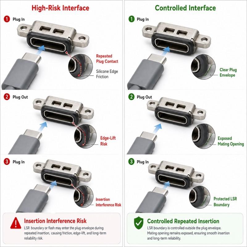
A port may look acceptable immediately after molding but develop insertion interference, silicone wear or edge lifting after repeated plug and unplug cycles if the silicone boundary is positioned too close to the mating path.
For a broader overview of this manufacturing method, review custom LSR overmolding for waterproof electronic components.
What Changes During Repeated Type-C Plugging?
Repeated plugging does not normally damage a correctly designed interface through one single insertion.
The risk comes from small loads being repeated around the same area.
Possible repeated loads include:
• Plug insertion
• Plug removal
• Small side loading
• Plug misalignment
• Connector rocking
• User pulling at an angle
• Local rubbing near the opening
• Repeated compression of the surrounding seal
• Cleaning around the port
• Dust or debris around the interface
One insertion may produce no visible damage.
After repeated use, an unstable interface may begin to show:
• Silicone edge wear
• Local edge lifting
• Increased insertion force
• Silicone flash entering the plug path
• Port-frame movement
• Uneven sealing contact
• Cosmetic damage near the opening
• Plug alignment variation
• Intermittent mating problems
The goal of DFM is therefore not only to confirm that the first plug can be inserted.
The interface should remain dimensionally and mechanically stable through the customer's defined plugging-cycle requirement.
Why Must the Type-C Mating Opening Remain Completely Clear?
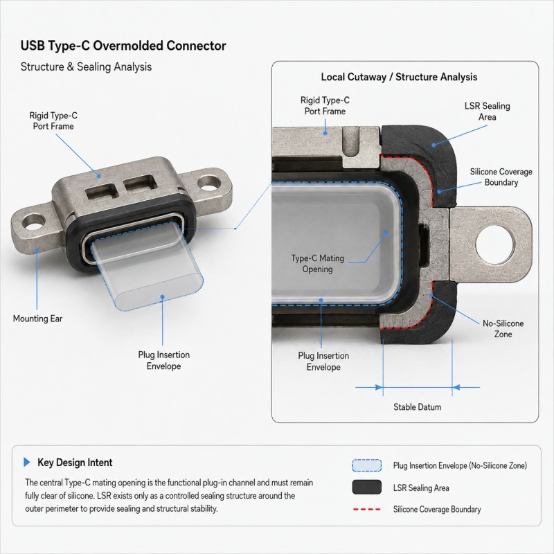
The Type-C mating opening is a functional no-silicone zone.
The plug requires a controlled insertion envelope around the rigid port geometry.
Silicone should not reduce this envelope unless the product has been specifically designed and validated for intentional silicone contact.
Possible interference around the opening includes:
• Thin silicone flash
• Silicone boundary shift
• Uneven overmold thickness
• Port insert tilt
• Mold mismatch
• Parting-line flash
• Local silicone edge deformation
A very thin silicone film may be difficult to see but can still affect plug insertion or the final mating position.
The drawing should therefore define:
• Type-C opening geometry
• Plug insertion envelope
• Silicone coverage boundary
• Minimum clearance from the plug path
• Port-frame datum
• Shut-off position
• Allowed flash condition
A statement such as “keep the Type-C opening clean” is not enough for precision tooling.
For a broader functional-area design method, review how no-silicone zones should be designed in LSR overmolding.
How Should the Silicone Coverage Boundary Be Positioned?
The silicone boundary should provide enough material for the intended sealing function while remaining outside the critical plug insertion path.
Important design variables include:
• Distance from the Type-C opening
• Silicone boundary width
• Local silicone thickness
• Port-frame geometry
• Housing support
• Plug insertion direction
• Available product space
• Mold shut-off width
• Parting-line position
• Final assembly interface
Moving the silicone farther away from the port is not automatically better.
If the sealing boundary is too far from the interface that requires protection, the waterproof path may become ineffective.
Moving the silicone closer to the port is not automatically better either.
If the silicone enters the real plug or housing mating envelope, it can increase insertion force or become exposed to repeated rubbing.
The correct boundary is therefore determined by the complete port, housing and mating-plug assembly.
It should be dimensioned from a stable rigid datum rather than from an irregular silicone edge or visual reference.
Why Does Type-C Port Insert Positioning Matter?
A precision mold can have the correct shut-off geometry and still produce insertion problems if the rigid Type-C port insert moves during LSR injection.
Possible movement includes:
• Horizontal shift
• Vertical shift
• Tilt
• Rotation
• Local frame deformation
• Incorrect manual loading
If the port moves, the silicone boundary moves relative to the central opening.
Possible results include:
• Silicone closer to one side of the opening
• Uneven clearance around the plug path
• Different seal thickness from left to right
• Local flash
• Different insertion force between samples
• Cosmetic asymmetry
• Unstable final assembly
The mold should therefore locate the port from stable rigid features.
Support should also be placed close enough to the overmolding region to prevent injection flow from pushing or tilting the insert.
For a detailed review of this control point, see how insert positioning affects custom LSR overmolding quality.
How Can Repeated Plugging Damage the Silicone Edge?
The silicone termination edge is most vulnerable when it lies directly in the repeated plug contact path.
During normal insertion, the Type-C plug should primarily engage with the rigid mating structure.
If the plug repeatedly rubs against an unsupported silicone edge, the boundary may experience:
• Sliding friction
• Local peeling
• Compression
• Edge stretching
• Surface wear
• Small tearing loads
This does not mean that every silicone edge near a Type-C opening will fail.
The risk depends on the real plug trajectory, port geometry, silicone support and edge location.
Where possible, the silicone boundary should be supported by the rigid carrier and positioned outside the primary plug contact path.
The termination should also avoid an unnecessary thin unsupported feather edge.
A controlled edge with sufficient moldability and rigid support is generally more repeatable than an edge that depends on extremely thin silicone to remain intact during repeated insertion.
Why Is Mold Shut-Off Critical Around a Type-C Opening?
The mold shut-off prevents liquid silicone from entering the Type-C mating opening.
This region can be difficult because the shut-off may need to follow a small rigid port frame with limited available contact width.
Possible shut-off risks include:
• Narrow sealing contact
• Port-frame dimensional variation
• Burrs or edge damage
• Insert tilt
• Parting-line mismatch
• Mold wear
• Contamination on the shut-off surface
• Local frame deformation
When a small gap opens, liquid silicone may enter and form flash or a thin film near the insertion opening.
The corrective action should therefore address the actual gap source.
Simply trimming the silicone after molding does not correct unstable port positioning or shut-off geometry.
For mass production, the mold and port insert must maintain repeatable contact across the realistic incoming part tolerance range.
USB Type-C Port LSR Overmolding DFM Checklist
| DFM Item | What Engineers Should Confirm | Main Risk |
Type-C opening | Plug mating envelope is fully defined | Silicone blocks insertion |
Silicone coverage | Boundary is dimensioned from a rigid datum | Coverage variation |
Plug path | Real insertion direction is available | Coverage variation |
Insert position | Port frame is located and supported | Uneven clearance |
Local wall thickness | LSR can fill and remain durable | Thin-edge tearing |
Shut-off | Stable contact exists around protected opening | Flash or silicone film |
Parting line | Kept away from critical mating edge where possible | Insertion interference |
Port tolerance | Incoming rigid frame variation is reviewed | Shut-off instability |
| Edge support | Silicone termination has rigid backing | Peel or wear |
| Final housing | Overmold is evaluated with enclosure assembly | Seal mismatch |
| Validation | Plugging, insertion and leak tests are defined | Sample passes but use fails |
The silicone mold design and tooling review should confirm the Type-C port datum, plug insertion envelope, silicone coverage boundary, insert support, mold shut-off, parting line, gate, venting and demolding before mold steel is finalized.
How Should Type-C Port Overmolding Be Validated?
Type-C port overmolding should be validated using the real or representative mating plug and final product assembly.
Recommended validation includes:
1. Opening Inspection
Confirm that the complete Type-C mating opening remains free from silicone film, flash and contamination.
2. Dimensional Inspection
Measure port position, silicone boundary, opening clearance and critical assembly dimensions.
3. Plug Insertion Test
Confirm that the mating plug enters and reaches its intended final position without abnormal silicone contact.
4. Insertion and Removal Force Review
Where required by the product specification, monitor whether the overmolded structure changes the expected mating behavior.
5. Repeated Plugging Test
Complete the customer's defined insertion and removal cycles and inspect the silicone boundary afterward.
6. Silicone Edge Inspection
Check for edge wear, lifting, tearing or permanent deformation.
7. Final Assembly and Leak Testing
Evaluate the waterproof function in the complete housing according to the actual product test method.
8. Pilot-Production Validation
Compare multiple mold cavities, consecutive molding cycles and realistic incoming port lots before mass-production approval.
The plugging-cycle count and acceptance limits should come from the actual product requirement rather than a generic number copied from another interface.
How SiliconePlus Supports Precision Electronic Interface Overmolding
SiliconePlus supports custom precision electronic-interface LSR overmolding projects from drawing and insert review through tooling, sampling, inspection and mass production.
Project support can include:
• Interface and silicone coverage review
• Functional no-silicone-zone definition
• Insert datum and positioning review
• Plug-clearance DFM
• Silicone edge and wall-thickness review
• Mold shut-off design
• Parting-line review
• Gate and venting analysis
• Precision mold development
• LSR injection molding
• Dimensional and appearance inspection
• Assembly and functional test support
• Pilot-production validation
Specific interface dimensions, silicone coverage, plugging-cycle requirements, waterproof conditions and acceptance criteria should always be confirmed according to the customer's real component and final device assembly.
FAQ
Can LSR Cover the Inside of a USB Type-C Opening?
The actual plug insertion and functional mating areas should remain clear unless intentional silicone contact is specifically part of the validated connector design.
Why Can a Type-C Port Work During Sampling but Become Difficult to Insert in Production?
Possible causes include insert-position variation, silicone-boundary shift, flash, incoming port tolerance or mold shut-off variation.
Can Silicone Flash Be Trimmed from the Type-C Opening?
Secondary trimming may be possible in some structures, but precision mating areas should not depend on unstable manual trimming as the primary process control.
Does Repeated Plugging Always Damage the Silicone?
No. A properly positioned and supported silicone boundary can remain outside the main plug load path. The risk increases when repeated rubbing or peeling is concentrated at the silicone edge.
Should the Type-C Plug Touch the Silicone Seal?
Only if that contact is intentional and validated as part of the product design. Otherwise, the plug path should normally remain clear of unintended silicone interference.
How Many Plugging Cycles Should Be Tested?
There is no universal cycle count for every product. The customer should define the required cycling condition according to the actual device, mating plug and intended use.
Conclusion
A reliable LSR overmolded USB Type-C port seal must protect the electronic interface without becoming part of an uncontrolled plug interference path.
The design should coordinate:
• Type-C mating opening
• Plug insertion envelope
• Silicone coverage boundary
• Port insert positioning
• Silicone edge support
• Mold shut-off
• Parting-line control
• Incoming port tolerance
• Repeated plugging
• Final waterproof validation
The central Type-C opening and required mating geometry should remain functional, while LSR is limited to the sealing or protective region required by the product structure.
These requirements should be reviewed during DFM before tooling, when the silicone boundary, shut-off and insert support can still be optimized efficiently.
Developing a Waterproof Electronic Interface?
If you are developing a Type-C, USB or another compact electronic interface requiring precision LSR overmolding, send your interface drawing, insert file, silicone coverage area, mating requirements and estimated quantity to the SiliconePlus engineering team for a project-specific DFM review.