Why Do PA-Supported LSR Pressure Diaphragms Show Hysteresis and Deflection Drift?
Answer Excerpt
An LSR pressure diaphragm may show hysteresis when its deflection at a given pressure differs between the loading and unloading stages. It may also show deflection drift when its response or reference position changes during a pressure hold or after repeated cycles.
These behaviors should be evaluated separately.
Hysteresis does not automatically mean the diaphragm is defective. Silicone is an elastomeric, viscoelastic material, so its response can depend on the loading history, test rate and temperature.
However, excessive or unstable variation may indicate that the membrane geometry, material selection, support conditions or manufacturing process needs further evaluation.
For a PA-supported LSR pressure diaphragm, engineers should review:
• Effective membrane diameter
• Membrane thickness and thickness uniformity
• Silicone hardness and material formulation
• Rigid PA support frame geometry
• Membrane-to-frame transition
• Bonding or mechanical retention
• Insert positioning during molding
• Pressure loading and unloading rate
• Temperature and operating medium
• Repeated-cycle requirements
• Test fixture and measurement method
The objective is to produce a repeatable pressure-responsive component that meets the customer's defined performance limits.
The correct acceptance criteria must be based on the finished assembly and its intended application rather than on appearance or generic silicone material properties alone.
What Is the Difference Between Diaphragm Hysteresis and Deflection Drift?
Hysteresis and drift are related to diaphragm response, but they are not interchangeable terms.
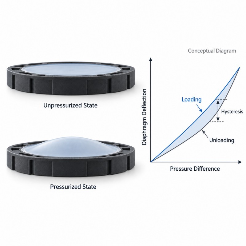
Hysteresis describes the difference between loading and unloading behavior under a defined test procedure.
For example, when pressure increases from a reference condition to a specified level, the diaphragm moves.
When pressure is reduced, the diaphragm may not follow exactly the same pressure-deflection path.
The separation between the two measured paths represents hysteresis under those particular test conditions.
Deflection drift describes a change in the observed response over time or repeated use.
Depending on the measurement method, this may include:
• Displacement change during a constant-pressure hold
• Change in the unloaded reference position
• Change in deflection at the same applied pressure after cycling
• Progressive response variation between test intervals
Creep is another relevant behavior.
During a sustained load, a viscoelastic membrane may continue to deform gradually.
After the load is removed, recovery can take time.
A component may exhibit hysteresis without unacceptable long-term drift, and a component may drift because of a changing assembly condition rather than a change in the silicone material itself.
For reliable diagnosis, engineers must define exactly which response is changing and how it is measured.
1.Define the Required Pressure-Deflection Response Before Tooling
The first step is to define what the diaphragm is expected to do.
A pressure diaphragm may be used to transmit movement, respond to a pressure difference or form part of a mechanical regulating assembly.
Its required behavior depends on the finished device.
A silicone over plastic design may integrate the flexible LSR membrane with a rigid PA support frame, but that manufacturing method does not establish the required pressure response by itself.
The customer should define:
• Operating pressure difference
• Maximum permitted pressure
• Effective membrane area
• Required deflection range
• Allowed response variation
• Permitted hysteresis
• Permitted zero-position or span drift
• Pressure loading direction
• Expected cycling frequency
• Pressure-hold requirements
• Operating temperature
• Working gas or liquid
• Required service life
The specifications should also identify the reference condition for dimensional and functional measurements.
Without these inputs, it is difficult to determine whether an observed response difference is acceptable material behavior or a functional failure.
The performance target should be agreed before the PA frame and LSR membrane geometry are finalized.
2.Membrane Thickness and Effective Diameter Change the Response
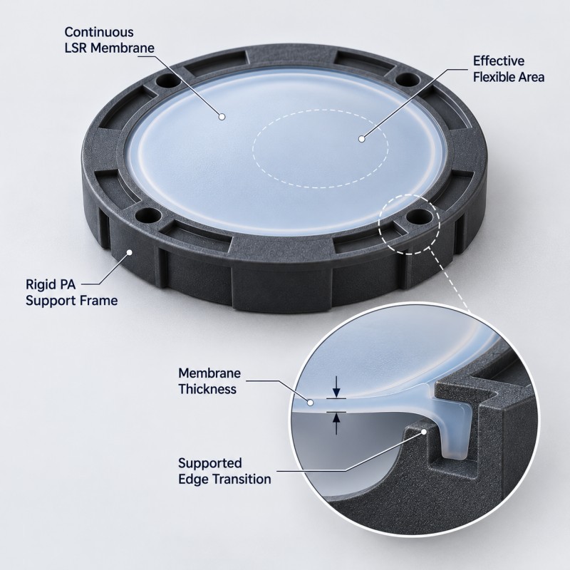
The central flexible membrane is the main deformation area of the component.
Its response depends on both material properties and geometry.
Important dimensions include:
• Effective unsupported diameter
• Nominal membrane thickness
• Thickness distribution
• Membrane curvature
• Edge transition geometry
• Support boundary position
• Available movement clearance
A thinner membrane may offer greater deflection under a given pressure difference, but it may also experience greater local strain.
A thicker membrane may reduce deflection, although the complete response also depends on its shape and boundary conditions.
Thickness variation is particularly important in precision LSR manufacturing.
If one area of the membrane is thinner than another, the diaphragm may deform asymmetrically.
Potential results include:
• Uneven pressure response
• Localized bending
• Nonuniform strain
• Different deflection between mold cavities
• Increased risk of local fatigue
• Variation after repeated pressure cycles
For this reason, a diaphragm should not be approved based only on its overall outside diameter and visible appearance.
The effective flexible area and membrane thickness distribution must be controlled according to the functional drawing.
3.The PA Support Frame Determines the Membrane Boundary Condition
A PA support frame provides a rigid or comparatively stiff structural boundary around the flexible silicone membrane.
The frame supports positioning, handling and installation.
However, it also affects how the membrane is constrained.
Engineers should review:
• PA material grade
• Frame stiffness
• Ring flatness
• Support width
• Inner edge radius
• Assembly locating surfaces
• Housing contact area
• Dimensional stability
• Retention of the silicone around the frame
If the support ring deforms during assembly, the effective membrane boundary may change.
That can affect the measured pressure-deflection relationship even when the silicone membrane itself has not changed.
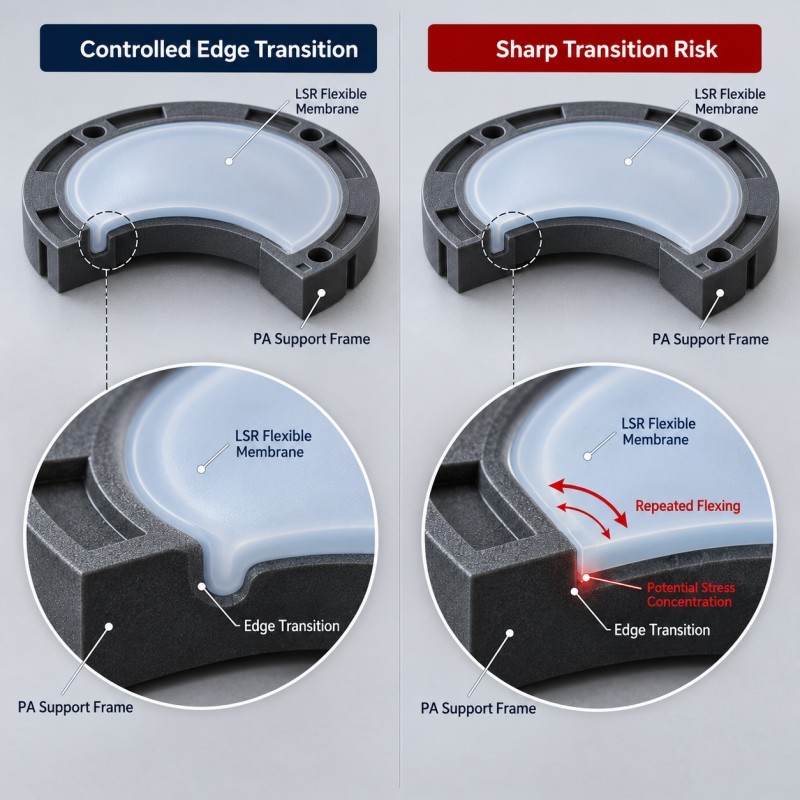
A sharp transition between the flexible membrane and rigid frame may also concentrate strain during repeated movement.
The interface should therefore be designed with a controlled transition and sufficient support.
Bonding or mechanical retention must be evaluated according to the actual material grades and operating loads.
The PA frame should not be assumed compatible with every LSR molding temperature or bonding system simply because it belongs to the polyamide material family.
4.Material Grade and Curing Consistency Must Be Controlled
Silicone hardness is only one indicator of elastomer behavior.
Two LSR compounds with similar nominal hardness may still respond differently in a specific diaphragm structure because their formulations and mechanical properties are not necessarily identical.
During LSR injection molding, consistent material preparation and curing conditions are important for repeatable production.
Project review may include:
• Silicone compound identification
• Material batch consistency
• Mixing and metering control
• Mold temperature
• Cure conditions
• Part thickness variation
• Any approved post-curing process
• Material storage requirements
• Relevant material test data
The relationship between material behavior and finished diaphragm response should be established using representative production samples.
A change in material grade, cure conditions or approved processing sequence may require additional functional verification.
Engineers should avoid selecting a compound solely because its Shore A hardness appears suitable.
The actual pressure-deflection curve, recovery behavior and cycling stability are more useful for confirming suitability in a pressure-responsive component.
5.Insert Positioning Can Change the Effective Membrane Geometry
In an integrated diaphragm, the PA frame is placed inside the mold before the silicone is formed.
Stable insert positioning is essential because the rigid frame defines the intended membrane boundary.
If the frame is tilted, shifted or incompletely seated during molding, the resulting component may have:
• Uneven membrane thickness
• An off-center flexible area
• Variable silicone coverage around the ring
• Localized thin transitions
• Inconsistent support geometry
• Variation in final assembly height
These issues may not be obvious from the external product appearance.
A diaphragm can look circular and complete while its effective flexible span is not uniform.
Mold locating surfaces should therefore reference stable features of the PA insert.
The process should also account for dimensional variation in incoming plastic frames.
For multi-cavity tooling, engineers should compare the membrane geometry and functional response across cavities.
A consistent pressure-deflection response requires both the silicone molding process and the rigid insert geometry to be repeatable.
6.Assembly Preload and Trapped Pressure Can Affect Test Results
Not every unexpected pressure-deflection result is caused by the molded diaphragm.
The test fixture and final mechanical assembly can influence the response.
Potential sources of variation include:
• Different clamping force
• Uneven housing closure
• Support-ring distortion
• Inconsistent reference pressure
• Trapped air in the test cavity
• Leakage in the fixture
• Temperature variation
• Sensor or displacement-gauge calibration
• Incorrect measurement datum
• Different loading rates
For example, two nominally identical diaphragms may show different measured displacement if their support frames are clamped under different conditions.
Similarly, a changing reference pressure can affect an apparent deflection measurement.
The test arrangement should therefore reproduce the intended boundary condition.
The measurement method should specify whether the reported displacement is referenced to the unloaded membrane, the rigid support frame or another fixed datum.
When unexpected drift appears, engineers should first confirm that the test fixture, pressure reference and assembly conditions are stable.
This avoids modifying the membrane design to compensate for a measurement or installation problem.
7.Repeated Pressure Cycling Should Be Evaluated Separately From Static Loading
A static pressure hold and a repeated pressure-cycle test evaluate different aspects of diaphragm behavior.
During a static hold, the main concern may be continued deformation, leakage or changes in the held position.
During repeated cycling, engineers may need to evaluate:
• Changes in pressure-deflection response
• Changes in unloaded reference position
• Hysteresis variation
• Recovery time
• Edge fatigue
• Local tearing
• Interface separation
• Leakage
• Dimensional change
• Functional response after environmental exposure
A cycle count alone is not a complete durability specification.
The test plan should define:
• Minimum and maximum pressure
• Pressure direction
• Loading and unloading rate
• Cycle frequency
• Temperature
• Working medium
• Number of cycles
• Inspection intervals
• Acceptance limits
If the diaphragm requires preconditioning before measurement, that procedure should be documented and applied consistently.
Testing should distinguish temporary recovery behavior from a change that remains after the defined recovery period.
The final acceptable variation depends on the customer's actual pressure-control or sensing application.
8.Demolding Damage May Become Visible Only During Cycling
Thin silicone membranes can be sensitive to removal forces during the molding process.
Even when a component appears complete immediately after production, localized damage may become more apparent during repeated movement.
Potential demolding defects include:
• Small tears near the membrane edge
• Local stretching
• Distorted flexible sections
• Damage near an undercut
• Silicone separation from the PA frame
• Uneven membrane recovery
• Flash affecting the supported boundary
A small defect near the rigid-to-flexible transition may experience repeated strain during pressure cycling.
The resulting damage can be mistaken for a material-selection problem.
Tooling review should therefore consider:
• Demolding direction
• Available release surfaces
• Membrane support
• Parting-line placement
• Edge radii
• Mold surface condition
• Handling after demolding
• Visual inspection of thin sections
When reviewing demolding defects, it is important to evaluate both the molded geometry and the method used to release the component from the tool.
The initial sample inspection plan should include the thin membrane, perimeter interface and any areas subjected to significant release strain.
9.How Should Pressure-Deflection Hysteresis and Drift Be Measured?
A repeatable pressure-deflection test should use a defined procedure and stable boundary conditions.
A practical test sequence may include the following stages.
First, install the diaphragm in a controlled fixture that represents the intended support condition.
Second, establish the reference pressure, temperature and unloaded displacement.
Third, apply the specified pressure sequence while measuring diaphragm movement.
Fourth, reduce pressure using the defined unloading procedure and record the displacement at corresponding pressure points.
Fifth, compare the loading and unloading curves to evaluate hysteresis under the selected conditions.
Sixth, repeat the pressure sequence according to the approved cycle plan.
Seventh, measure the pressure-deflection response again at the specified inspection intervals.
Eighth, assess unloaded reference position, response change, leakage and physical damage.
The test report should identify:
• Part number and revision
• Silicone and PA material identification
• Sample and cavity identification
• Test fixture
• Pressure measurement method
• Displacement measurement method
• Temperature
• Pressure sequence and rate
• Preconditioning procedure
• Cycle count
• Recovery interval
• Measured results
• Customer acceptance criteria
The loading and unloading curves can be plotted to show the observed response.
However, no universal hysteresis percentage or allowable drift should be assumed for all LSR diaphragms.
The acceptable limits must come from the intended device function.
| Observed Behavior | Possible Factors to Investigate | What to Check |
Different loading and unloading curves | Material viscoelasticity, test rate, temperature | Repeatable pressure-deflection test |
Increasing deflection during a hold | Creep, assembly movement, pressure-reference change | Time-based displacement and fixture stability |
Changed unloaded position after cycling | Recovery time, permanent deformation, interface change | Defined recovery interval and dimensional check |
Different response between cavities | Membrane thickness, insert position, process variation | Cavity-by-cavity inspection |
Asymmetric membrane movement | Thickness variation, off-center support, fixture alignment | Geometry and test alignment |
Edge cracking or tearing | High local strain, sharp transition, demolding damage | Edge inspection and cycle test |
Silicone lifting from PA frame | Bonding or retention weakness, repeated edge stress | Interface and material review |
| Unexpected leakage | Interface defect, tear, assembly issue | Assembly leak test |
| Different response at different temperatures | Material response and assembly dimensional change | Temperature-controlled testing |
| Unstable test repeatability | Fixture, pressure control, measurement method | Measurement-system review |
When Is an Integrated PA-Supported LSR Diaphragm Worth Considering?
An integrated pressure diaphragm may be suitable when the flexible membrane must remain accurately positioned within a rigid mounting structure.
Compared with separately installing a loose silicone membrane, an integrated PA support frame may help reduce membrane positioning variation and simplify component handling.
Potential applications include:
• Industrial pressure regulation mechanisms
• Pneumatic control assemblies
• Pressure-responsive mechanical switches
• Compact fluid-control equipment
• Custom mechanical monitoring systems
The integrated approach should be evaluated against the actual assembly requirements.
Important considerations include:
• Pressure-responsive membrane geometry
• Support frame stiffness
• PA and LSR material compatibility
• Required deflection
• Adhesion or mechanical retention
• Working medium
• Operating temperature
• Cycle-life requirements
• Production volume
• Tooling feasibility
SiliconePlus provides custom LSR overmolded pressure diaphragms with PA support frames for drawing-based industrial applications.
The manufacturing scope covers the customized flexible silicone and plastic support component, not a complete pressure regulator or calibrated pressure sensor.
Final pressure range, response accuracy, hysteresis and service life must be validated for the customer's application.
What Should Be Included in an LSR Pressure Diaphragm RFQ?
To evaluate an integrated LSR pressure diaphragm, the customer should provide the functional requirements as well as the component geometry.
Recommended project inputs include:
• 2D component drawing
• 3D CAD model
• Effective membrane diameter
• Nominal and critical membrane thickness
• PA support-frame drawing
• PA material grade
• Silicone material requirements
• Required pressure-deflection response
• Maximum allowable deflection
• Permitted hysteresis and drift
• Loading and unloading conditions
• Pressure-cycle requirements
• Working medium
• Operating temperature
• Mating housing geometry
• Required leak or functional tests
• Inspection and acceptance criteria
• Estimated production quantity
• Annual volume forecast
If an existing diaphragm shows unstable behavior, provide the original test procedure and any pressure-deflection measurements.
This information helps distinguish whether the issue is related to material behavior, membrane geometry, insert positioning, assembly or the test method.
A useful quotation should identify which requirements can be evaluated during molding feasibility review and which require customer-side system validation.
Frequently Asked Questions
Is Hysteresis Always a Defect in an LSR Pressure Diaphragm?
No. Silicone is a viscoelastic elastomer, and loading and unloading behavior can differ under defined test conditions. The acceptable level of hysteresis depends on the customer's functional requirements and measurement method.
Can Membrane Thickness Affect Pressure-Deflection Response?
Yes. The effective membrane thickness, unsupported diameter, geometry and material properties influence its response. Thickness variation may also contribute to differences between samples or mold cavities.
Why Does the PA Support Frame Matter?
The PA support frame defines the membrane's mounting and boundary conditions. Frame distortion, assembly variation or an unstable silicone-to-PA interface may change the effective flexible area and measured response.
Can an LSR Pressure Diaphragm Recover After a Pressure Hold?
Recovery depends on the silicone compound, geometry, load, temperature and time. A specified recovery interval should be included in the test procedure when evaluating unloaded position or residual deformation.
How Should Repeated-Cycle Performance Be Validated?
The test should define pressure range, loading rate, cycle frequency, temperature, working medium, cycle count, measurement intervals and acceptance criteria. Inspect pressure-deflection response together with physical condition and leakage where applicable.
Does SiliconePlus Supply a Standard Pressure-Rated Diaphragm?
SiliconePlus provides custom LSR overmolded diaphragm manufacturing based on customer drawings and application requirements. A specific pressure rating, response accuracy or cycle life must be established and validated for the finished design.
Conclusion
Hysteresis and deflection drift in an LSR pressure diaphragm should be evaluated as measurable responses of the complete component and assembly, not treated as one general silicone defect.
A reliable investigation should consider:
• Silicone material behavior
• Effective membrane diameter
• Membrane thickness uniformity
• PA support-frame geometry
• Silicone-to-plastic interface
• Insert positioning
• Molding and curing consistency
• Demolding condition
• Test fixture and assembly preload
• Pressure loading history
• Temperature and working medium
• Repeated-cycle validation
The key is to establish a consistent measurement method and define the permitted response variation before tooling and production approval.
A successful diaphragm is not simply one that moves under pressure.
It is one that provides the required response consistently under the customer's specified loading, environmental and service conditions.
Developing a Custom PA-Supported LSR Pressure Diaphragm?
If you are developing a custom pressure-responsive membrane, industrial pneumatic component or LSR diaphragm with a rigid plastic support frame, please share your 2D/3D drawings, PA material grade, membrane geometry, operating medium, pressure-deflection requirements, cycling conditions and estimated production quantity.
You can contact SiliconePlus to discuss LSR overmolding feasibility, material compatibility, PA insert positioning, tooling development, prototype sampling and production requirements.