Why Does LSR Overmolding Produce Flash Around Plastic Inserts?
Answer Excerpt
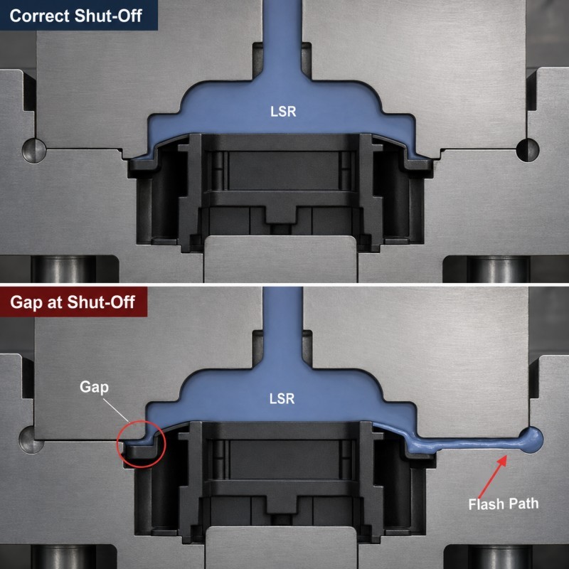
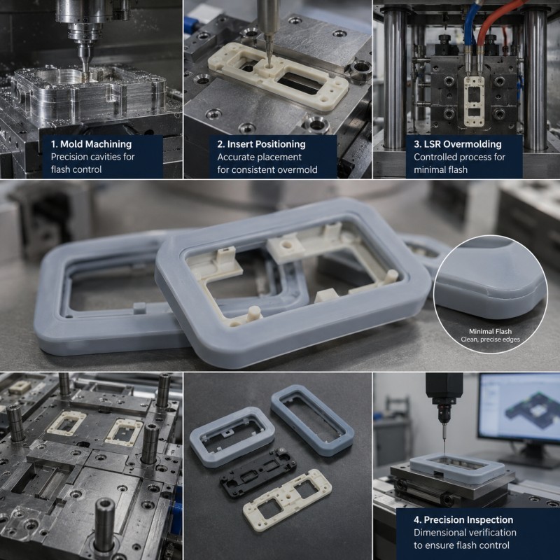
LSR overmolding flash around plastic inserts normally forms when uncured silicone enters a small gap between the mold shut-off and the insert surface. The gap may be caused by plastic dimensional variation, warpage, unstable positioning, insufficient insert support, mold wear or excessive local cavity pressure. Reliable flash control requires the plastic insert, mold and molding process to be designed as one tolerance-controlled system.
Liquid silicone rubber can flow into thin sealing lips, narrow grooves and complex retention structures. This flowability is one of the main advantages of LSR injection molding.
However, the same material can also enter very small uncontrolled gaps.
A plastic insert may appear acceptable before molding, but dimensional variation, residual stress or thermal deformation can change the shut-off condition after it is loaded into the heated mold.
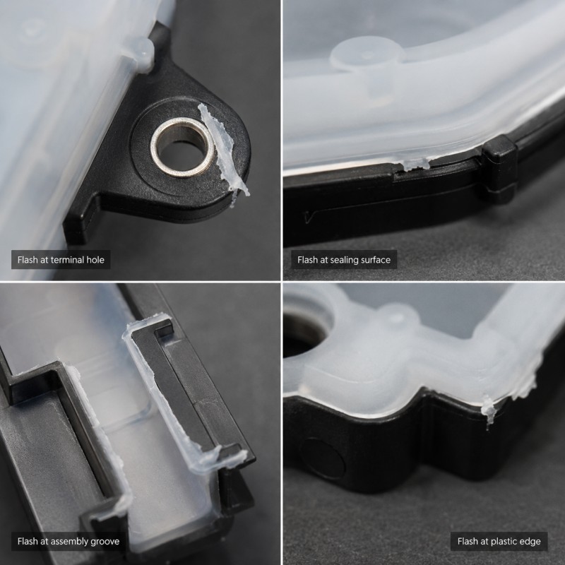
Even a thin silicone film may create serious problems around connector openings, sealing surfaces, assembly datums, terminal areas or cosmetic edges.
For projects requiring integrated sealing and multi-material molding, plastic with silicone overmolding should be reviewed before the mold structure is finalized.
What Problems Can LSR Flash Cause?
LSR flash is not only a cosmetic defect. Its effect depends on where the unwanted silicone appears and how the final component is assembled.
Flash Blocks a Functional Opening
Silicone may enter connector openings, terminal holes, screw holes, pressure ports, sensor windows or assembly slots.
Even a thin film may prevent installation or block the intended function.
Flash Changes a Sealing Surface
Uncontrolled silicone on a sealing land may prevent uniform compression or create an unintended leakage path.
Flash Interferes with Assembly
Silicone around a datum, snap feature, guide rail or connector edge may increase insertion force or prevent the parts from reaching the correct assembly position.
Flash Covers an Electrical Area
If silicone reaches terminals, contact pads or exposed conductors, it may cause failed electrical contact or unstable signal transmission.
Flash Creates an Uncontrolled Tear Edge
Thin flash may tear during handling or assembly. The torn edge can become a crack-starting point in the main silicone structure.
Flash Increases Manual Trimming
Manual trimming increases labor, handling damage and dimensional variation. It may also scratch the plastic insert or remove part of the functional silicone seal.
The best solution is therefore to prevent flash through DFM and process control instead of depending on secondary trimming.
Why Does Flash Form Around Plastic Inserts?
Flash forms when the mold cannot maintain a stable seal against the plastic insert during filling and curing.
The main engineering causes include:
• Excessive plastic dimensional tolerance
• Plastic insert warpage
• Unstable insert positioning
• Insufficient support beneath the shut-off
• Shut-off width that is too narrow
• Incorrect shut-off angle
• Excessive local injection pressure
• Gate flow pushing the insert
• Trapped air near the shut-off
• Mold wear or damage
• Contamination on the mold surface
• Plastic or silicone material changes
• An unstable molding process window
The defect should be investigated as a combined insert, tooling and process problem rather than blamed only on the silicone material.
1. Plastic Insert Tolerance Is Too Large
The mold shut-off is normally designed according to a specified plastic dimension.
If the incoming insert is smaller, thinner or more warped than expected, the mold may not contact it completely.
A gap then forms between the steel and plastic surface.
Relevant plastic dimensions may include:
• Wall thickness
• Housing width
• Local flatness
• Terminal-hole size
• Rib height
• Insert outline
• Datum position
• Parting-line mismatch
• Stiffener thickness
• Cable or tube diameter
The DFM review should not use only nominal dimensions.
Engineers should evaluate the minimum and maximum plastic conditions and determine whether the shut-off remains functional across the full tolerance range.
For high-volume production, actual process capability of the plastic part is more useful than a drawing tolerance that is technically allowed but rarely achieved.
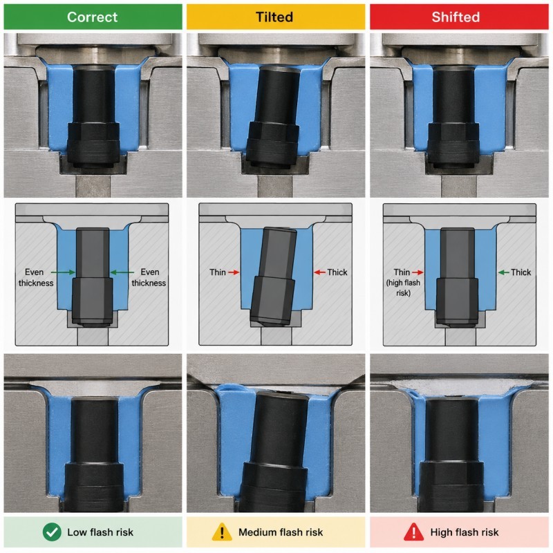
2. Insert Positioning Is Not Repeatable
A plastic insert can meet its dimensional specification and still produce flash if it is not loaded into the mold consistently.
Possible positioning problems include:
• Insert not fully seated
• Incorrect orientation
• Locating hole not engaged
• Plastic housing tilted
• Cable or terminal pulling the insert
• Datum surface contaminated
• Insert lifted during mold closing
• Injection flow moving the insert
• Manual loading variation
The mold should locate the insert using stable and repeatable datums.
Positioning features should be close to the critical shut-off area so that small insert movement cannot create a large gap.
The fixture should also support the insert without damaging the plastic, terminal or functional surface.
Insert positioning affects custom LSR overmolding quality because movement can change silicone thickness, flash, bonding area and final dimensions.
3. The Mold Shut-Off Surface Is Too Narrow or Unstable
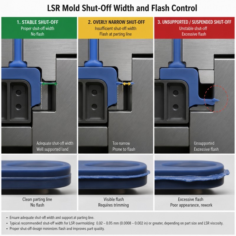
The shut-off surface is the mold-to-insert contact area that stops silicone from entering a protected zone.
If this surface is too narrow, a small insert variation or local pressure increase can open the seal.
High-risk shut-off conditions include:
• Narrow contact width
• Sharp or unsupported plastic edge
• Shut-off crossing a plastic step
• Contact on a textured surface
• Contact on a molded parting line
• Contact close to a weak plastic wall
• Shut-off across a curved surface
• Insufficient steel strength
• Difficult mold-cleaning access
A suitable shut-off should contact a rigid, repeatable and measurable plastic surface.
The mold designer should also consider steel wear, insert loading and future maintenance.
Where possible, critical shut-off components should be designed as replaceable mold inserts so that worn areas can be repaired without rebuilding the entire mold.
4. The Plastic Insert Warps During LSR Molding
A plastic insert may be flat during incoming inspection but deform after it enters the heated LSR mold.
Plastic warpage can be caused by:
• Residual injection-molding stress
• Uneven plastic wall thickness
• Glass-fiber orientation
• Excessive insert temperature
• Long heating time
• Moisture absorption
• Weak unsupported walls
• Local injection pressure
• Uneven clamping
• Material-grade variation
When the plastic changes shape, the shut-off contact may open during filling.
The defect may appear only after several molding cycles because the insert temperature becomes more stable during continuous production.
Engineers should therefore check plastic dimensions before overmolding, immediately after molding and after the part returns to room temperature.
Thin walls and large flat housings may require additional mold support.
5. Local Cavity Pressure Opens the Shut-Off
Even a correctly positioned insert can produce flash if local cavity pressure exceeds the support available at the shut-off.
Excessive local pressure may be caused by:
• Gate placed too close to the shut-off
• High injection speed
• Excessive shot volume
• Long narrow flow path
• Unbalanced multi-cavity filling
• Blocked or insufficient venting
• Cold or partially cured material
• Incorrect runner balance
• Insert movement during filling
The objective is not simply to reduce pressure as much as possible.
The process must still fill thin silicone features, mechanical locks and sealing lips completely.
Gate position, filling sequence, insert support and venting should be optimized together to create a stable process window.
6. Gate and Vent Locations Are Incorrect
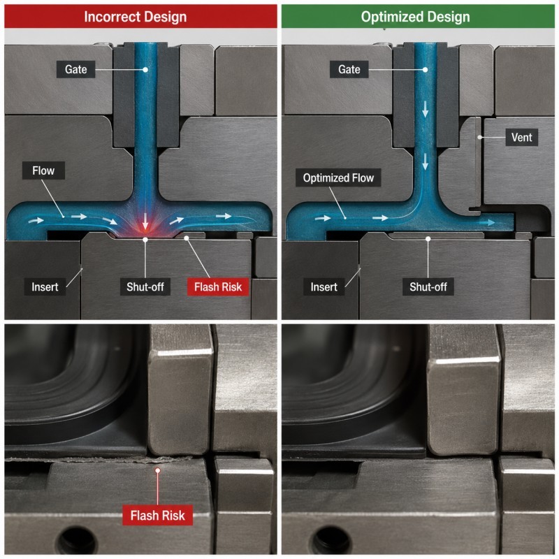
Gate location determines the direction and timing of silicone flow around the plastic insert.
If the gate directs the flow toward a weak shut-off, the material may force the insert away from the mold steel.
Poor gate design can cause:
• Local flash
• Insert movement
• Uneven silicone thickness
• Weld lines
• Air traps
• Short shots
• High cavity pressure
• Cosmetic gate marks
Vents should be located at final-fill positions and around closed-end grooves or retention structures.
Blocked or undersized vents can increase local pressure and push silicone toward the shut-off.
However, excessively deep vents may themselves create flash.
Gate and vent dimensions must be validated during sampling and monitored during production.
7. Mold Wear or Contamination Opens the Sealing Surface
A mold may produce acceptable first samples but gradually develop flash during mass production.
Possible causes include:
• Shut-off edge wear
• Locating-pin wear
• Insert-support damage
• Plastic burrs scratching the mold
• Incorrect mold cleaning
• Silicone residue on the shut-off
• Dust or foreign particles
• Misloaded inserts
• Excessive clamping
• Steel deformation
The maintenance plan should define:
• Cleaning frequency
• Approved cleaning tools
• Shut-off inspection method
• Wear limits
• Replaceable insert criteria
• First-piece inspection after maintenance
• Flash trend monitoring
• Mold-repair records
Operators should not use hard tools that scratch precision shut-off surfaces.
Small scratches can create continuous silicone leakage paths during molding.
8. Material or Process Changes Are Not Revalidated
A previously stable overmolding process may begin producing flash after a material or process change.
Relevant changes include:
• New plastic supplier
• Different plastic grade
• Different filler percentage
• New color masterbatch
• Recycled plastic content
• External mold release
• New LSR grade
• Silicone hardness change
• Different post-curing requirement
• Mold-temperature change
• Injection-speed change
• Different operator-loading method
The same part number does not guarantee identical surface condition or dimensional behavior.
Critical material and process changes should trigger a controlled revalidation rather than being introduced directly into mass production.
What Does a Reliable Mold Shut-Off Structure Look Like?
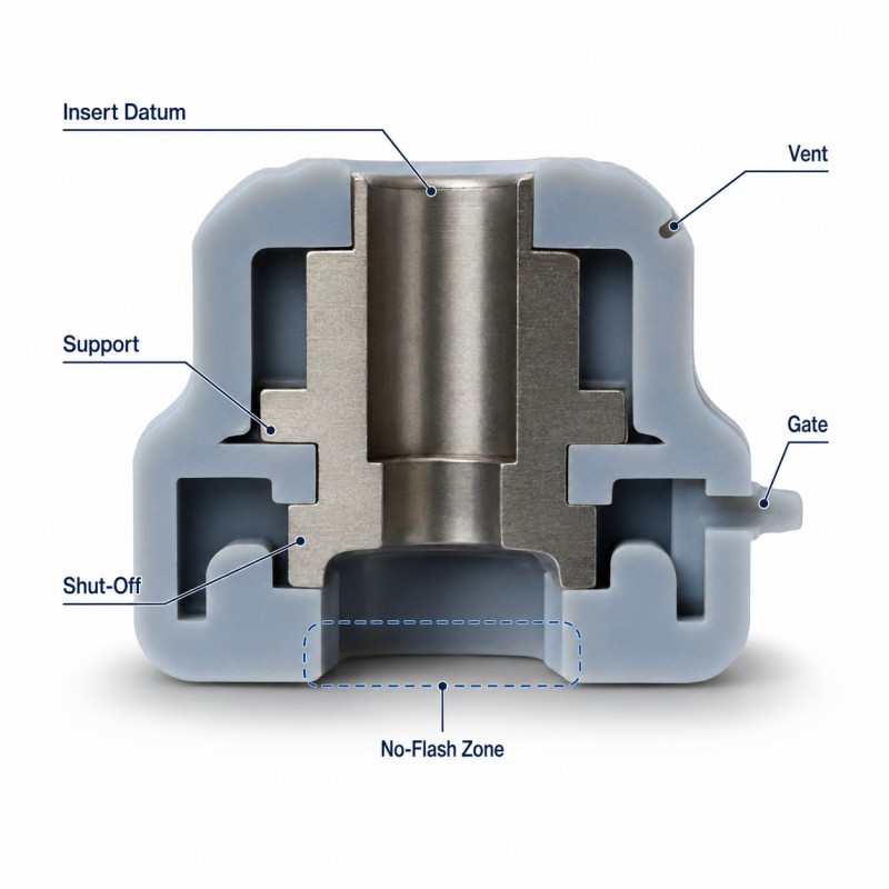
A reliable shut-off structure combines stable insert positioning, sufficient plastic support and a controlled mold-contact area.
Stable Plastic Datum
The insert should locate from repeatable surfaces that are not affected by cosmetic variation or flexible features.
Support Close to the Shut-Off
The plastic should be supported near the mold-contact area so that injection pressure cannot bend it away from the steel.
Sufficient Shut-Off Width
The contact area should be wide enough to tolerate realistic insert and process variation.
Suitable Shut-Off Angle
The mold should close without scraping or crushing the plastic insert.
Controlled Surface Finish
The contact region should be smooth and free from textures, burrs, ejector marks and irregular parting lines.
Replaceable Mold Inserts
High-wear shut-off areas should be replaceable where the mold structure permits.
Accessible Cleaning and Inspection
Operators should be able to clean and inspect the shut-off without damaging nearby precision surfaces.
Balanced Filling
The gate and flow path should avoid directing unnecessary pressure toward the critical shut-off.
DFM Checklist for Flash Control in LSR Overmolding
| DFM Item | What Engineers Should Confirm |
Plastic material | Exact resin, filler, color and supplier are confirmed |
Insert tolerance | Minimum and maximum dimensions are reviewed |
Flatness | Critical shut-off surfaces remain within a controlled range |
Insert datum | Stable and repeatable positioning references are available |
Insert support | Plastic cannot bend under injection pressure |
Shut-off width | Contact area is sufficient for production variation |
Shut-off position | Located on a rigid and measurable plastic surface |
Plastic warpage | Heat and residual-stress risks are evaluated |
Gate position | Flow does not push the insert away from the shut-off |
Venting | Air can escape without creating excessive flash |
Silicone thickness | Thin and thick sections are balanced |
Mechanical retention | Grooves and holes can fill without trapped air |
Mold wear | Critical shut-off parts can be inspected and repaired |
| Cleaning | Shut-off surfaces are accessible and protected |
| Material changes | Resin and LSR changes require revalidation |
| Acceptance standard | Flash size and critical no-flash zones are defined |
The silicone mold design and tooling review should be completed using the plastic drawing, tolerance report, resin data, silicone coverage map and critical no-flash areas.
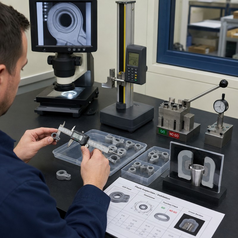
How Should Flash Control Be Validated?
Flash control should be validated using multiple plastic inserts, cavities, material lots and production cycles.
1. Visual Inspection
Inspect all critical shut-off areas under controlled lighting and magnification.
2. Dimensional Measurement
Measure the insert, silicone boundary and critical assembly dimensions before and after overmolding.
3. Flash Thickness or Width Check
Where required, define a measurable flash limit rather than using only a general cosmetic description.
4. No-Flash Functional Gauge
Use a connector, plug, pin, assembly fixture or dedicated gauge to confirm that silicone has not entered a functional area.
5. Cross-Section Inspection
Cross-section selected samples to evaluate shut-off contact, silicone thickness, voids and insert position.
6. Repeated-Cycle Production Trial
Run consecutive cycles to determine whether insert temperature, mold contamination or process drift increases flash.
7. Multi-Lot Insert Validation
Test plastic inserts from more than one production lot when incoming variation is expected.
8. Multi-Cavity Comparison
Compare all cavities for filling balance, flash location and dimensional consistency.
9. Assembly Test
Confirm that flash does not increase insertion force, interfere with datums or change seal compression.
10. Environmental Testing
For sealing products, repeat assembly, leak or adhesion testing after thermal cycling, humidity or mechanical loading.
Common Flash Problems and Corrective Actions
| Failure Symptom | Likely Cause | Recommended Action |
Flash appears on one side only | Insert tilt or uneven support | Improve datum and support near the shut-off |
Flash varies between plastic lots | Insert tolerance or warpage variation | Tighten incoming control and validate multiple lots |
Flash increases during continuous production | Insert heating or mold contamination | Check thermal deformation and cleaning frequency |
Flash appears near the gate | Excessive local pressure | Move or rebalance the gate and improve support |
Thin film blocks a hole | Small shut-off gap | Increase shut-off stability and use a functional gauge |
Plastic is marked or crushed | Shut-off is too tight | Review interference, angle and plastic support |
| Flash increases after mold maintenance | Shut-off damage or incorrect assembly | Inspect mold inserts and verify first pieces |
| One cavity produces more flash | Runner imbalance or cavity wear | Compare pressure, venting and shut-off condition |
| Samples pass but mass production fails | Process window is too narrow | Validate consecutive cycles and material variation |
Typical Applications
Flash control is especially important in precision multi-material components that contain functional openings, sealing surfaces or electrical interfaces.
Automotive Electronics
• Waterproof connector housings
• High-voltage components
• Sensor frames
• Charging-port components
• Wire-harness interfaces
Consumer Electronics
• Charging-port seals
• Waterproof buttons
• Speaker and microphone frames
• Camera-module components
• Wearable-device housings
Medical and Healthcare Devices
• Sensor housings
• Fluid-control components
• Electronic probe assemblies
• Device sealing frames
• Handheld equipment components
Industrial Equipment
• Waterproof sensor housings
• Electrical connectors
• Cable-entry components
• Control-panel seals
• Outdoor electronic modules
The acceptable flash standard should be defined according to the final product function rather than one universal cosmetic requirement.
How SiliconePlus Supports LSR Flash-Control Projects
SiliconePlus supports silicone-over-plastic projects from drawing review and DFM through tooling, sampling, inspection and mass production.
Project support can include:
• Plastic material and tolerance review
• Silicone coverage-map analysis
• Insert-positioning design
• Shut-off and flash-control review
• Plastic support design
• Gate and venting review
• Mechanical-retention design
• Precision mold manufacturing
• LSR injection molding
• Dimensional and appearance inspection
• Functional no-flash inspection
• Cross-section analysis
• Pilot-production validation
• Prototype-to-volume manufacturing support
SiliconePlus has more than 25 years of silicone manufacturing experience, in-house mold-processing capability, liquid silicone injection equipment and precision inspection resources.
Specific flash limits, tolerances, waterproof performance and production acceptance standards should be confirmed according to the actual plastic insert, silicone structure, assembly and test method.
FAQ
Is a Small Amount of LSR Flash Normal?
Some non-critical parting-line flash may be acceptable depending on the drawing and application. Functional openings, sealing surfaces and electrical areas may require a strict no-flash standard.
Why Does Flash Appear Only on One Side?
The insert may be tilted, warped or insufficiently supported. One-sided flash often indicates a positioning or local shut-off problem.
Can Higher Mold-Clamping Force Eliminate Flash?
Not always. Excessive force may damage the plastic insert or mold. The actual gap, support, shut-off and local pressure should be identified first.
Why Does Flash Increase After Several Production Cycles?
The insert may heat and deform, silicone residue may accumulate, or the process may drift as the mold reaches stable operating temperature.
Can Manual Trimming Solve the Problem?
Manual trimming may be acceptable for limited non-critical areas, but it should not be the primary control for functional surfaces or high-volume production.
How Can Plastic Warpage Be Checked?
Measure flatness and critical dimensions before overmolding, immediately after molding and after the component returns to room temperature.
Does Lower Injection Pressure Always Reduce Flash?
No. Pressure must remain sufficient to fill the complete silicone structure. Gate location, filling balance, support and venting should be optimized together.
What Information Is Needed for Flash-Control DFM?
Provide the plastic drawing, tolerance report, resin grade, 3D assembly, silicone coverage map, no-flash zones, annual volume and inspection requirements.
Conclusion
LSR flash around plastic inserts forms when the mold cannot maintain a stable shut-off during filling and curing.
Reliable flash control requires coordinated management of:
• Plastic insert tolerance
• Insert flatness and warpage
• Stable positioning
• Plastic support
• Shut-off width and location
• Gate and venting
• Local cavity pressure
• Mold wear and cleaning
• Material changes
• Production validation
The best time to prevent flash is during DFM, before mold steel is manufactured.
For a project-specific evaluation, send your plastic drawing, resin grade, silicone coverage map and critical no-flash areas to the SiliconePlus engineering team.