How Should LSR Overmolded Smart Glasses Temple Tips Be Designed to Maintain Frame Fit and Wearing Comfort?
Answer Excerpt
LSR overmolded smart glasses temple tips should be designed around two separate requirements: the rigid temple structure must maintain the frame's mechanical fit, while the silicone contact area must provide the intended soft-touch and cushioning function.
The key is to define the silicone coverage against stable frame datums, preserve hinge and electronic interfaces, control the overmolded geometry, and validate the finished component in the assembled eyewear. The silicone layer should not become an uncontrolled dimensional feature that changes the temple's fit or interferes with its functional components.
Why Must Frame Fit and Wearing Comfort Be Designed Separately?
Smart glasses combine a relatively compact rigid frame with electronic components and user-contact surfaces. The temple tip is therefore more than a cosmetic silicone cover.
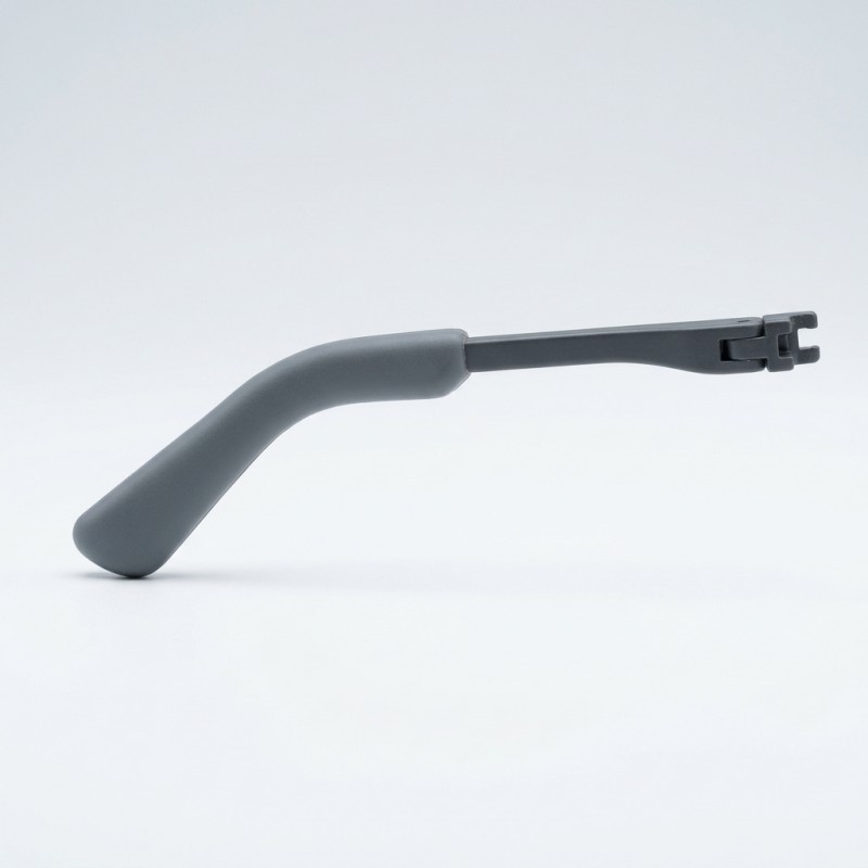
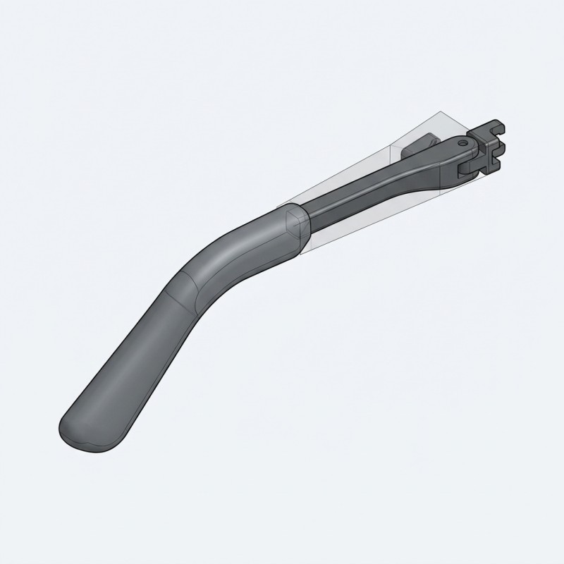
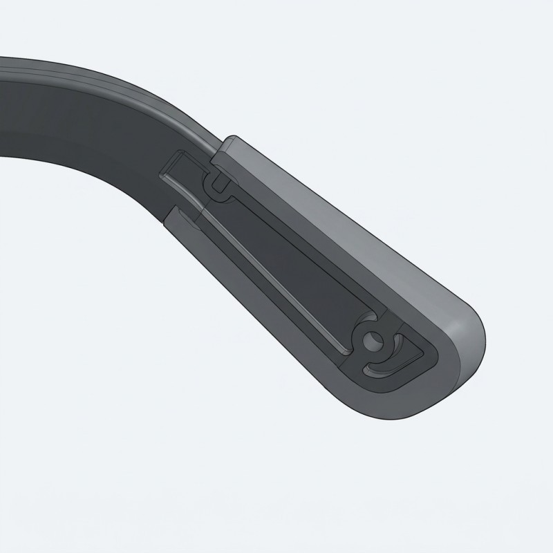
Its rigid insert helps define the temple's mechanical geometry. Its silicone overmold creates a localized contact surface around the rear section that rests against the ear.
If these two functions are not separated during design, a change in silicone thickness or coverage may affect the finished temple envelope, assembly clearance or the position of nearby functional features.
The product-specific custom LSR overmolded smart glasses temple tips developed by SiliconePlus use direct LSR overmolding onto selected areas of a plastic or metal temple insert. For related electronic-device projects, review our 3C electronics silicone customization solutions.
The design objective is to keep the rigid structure responsible for frame fit while using the silicone layer to achieve the intended contact geometry.
Which Dimensions Should Be Controlled by the Rigid Temple Insert?
The rigid temple insert should establish the primary dimensional references for the finished eyewear assembly.
Before mold development, engineers should identify the features that control the temple's position and fit. These references should remain measurable and repeatable after LSR overmolding.
The silicone contact area should be designed around these references rather than treated as the main locating feature for the complete frame.
Important dimensions and references include:
- The hinge connection and its mating position.
- The temple centerline and overall alignment.
- The rigid insert's external profile.
- The beginning and end of the intended ear-contact area.
- The maximum finished envelope of the silicone-overmolded section.
- The relationship between the left and right temple assemblies.
The dimensional review should include the actual mating frame or hinge component whenever possible. A temple tip that looks correct as an individual molded part may still create an assembly problem if the complete dimensional stack-up has not been considered.
Rigid Temple Design References
Design reference | What should be defined | Why it matters |
Hinge interface | Position, mating geometry and required movement | Maintains frame assembly and hinge function |
| Temple centerline | Reference direction and alignment | Helps maintain overall frame geometry |
Rigid insert profile | Main external dimensions and locating surfaces | Establishes the primary dimensional reference |
| Ear-contact boundary | Start and end of the silicone contact area | Controls where the soft-touch layer is located |
| Finished envelope | Maximum external profile after overmolding | Prevents interference with surrounding parts |
| Left/right reference | Relevant symmetry and assembly relationships | Supports consistent eyewear fit |
How Should the Silicone Coverage Zone Be Defined?
The silicone coverage zone should be defined on the complete temple assembly, not only on an isolated insert drawing.
For most temple-tip designs, the intended overmolded area is the rear contact section that rests against the ear. The coverage should provide the required contact surface without extending into areas that control hinge connection, fastening or electronic functions.
A practical design review should establish:
1. The exact start and end points of the silicone coverage.
2. The intended outer profile of the finished temple tip.
3. The relationship between the silicone layer and the rigid insert.
4. The areas that must remain exposed.
5. The transition between the rigid temple surface and the soft silicone contact area.
6. The dimensions that must be checked after molding.
For projects involving plastic with silicone overmolding, the rigid substrate and silicone geometry should be reviewed together. The final structure depends on the actual insert material, surface condition, molding feasibility and assembly requirements.
Do not assume that covering a larger area automatically improves comfort. The coverage boundary should be determined by the intended contact zone and the functional architecture of the eyewear.
Which Functional Areas Must Remain Uncovered?
Smart glasses contain functional areas that should not be treated as ordinary silicone coverage surfaces.
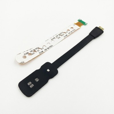
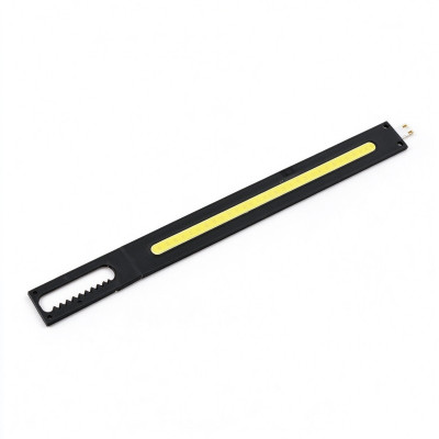
The product structure published by SiliconePlus identifies several areas that may need to remain accessible, including hinges, speaker openings, charging contacts and sensors.
These features should be marked as controlled no-silicone zones in the engineering drawings and three-dimensional model.
The tooling design should then be reviewed to ensure that the silicone does not enter these areas or interfere with their intended function.
This is especially important when a functional feature sits close to the rear temple-tip coverage boundary. A small change in the silicone edge or insert position may create interference that is difficult to identify from a simplified two-dimensional outline.
Functional Keep-Out Zones for Smart Glasses
| Functional area | Design requirement | Inspection focus |
Hinge and pivot area | Preserve the required mechanical interface and movement | Hinge movement and assembly clearance |
Speaker openings | Keep the intended sound openings unobstructed | Opening condition and silicone flash |
Charging contacts | Preserve electrical contact access | Contact exposure and accessibility |
| Sensors | Keep the specified sensing interface accessible | Coverage boundary and sensor access |
| Fastening and assembly surfaces | Preserve required mating and locating features | Assembly fit and interference |
| Silicone contact area | Apply LSR only to the intended region | Coverage, edge position and surface condition |
How Should the Silicone Edge and Thickness Transition Be Designed?
The transition between the rigid temple insert and the silicone contact area is one of the most important parts of the design.
An abrupt change in section geometry may create an uncomfortable ridge, an uneven external profile or a locally weak silicone edge. A poorly positioned transition may also affect the finished temple envelope.
The design review should consider the following:
1. Use a controlled transition
Where the product geometry allows, use a smooth transition between the rigid insert and the silicone-covered section. Avoid unnecessary sharp edges or abrupt changes in the external profile.
2. Control local silicone thickness
The silicone layer should be evaluated at the actual contact area, side edges and transition regions. A uniform appearance in a rendering does not prove that the molded section will have consistent thickness.
3. Avoid uncontrolled thin edges
Very thin silicone edges may be more sensitive to filling variation, tearing or edge lifting. The minimum practical geometry should be reviewed with the selected material and molding process.
4. Consider the parting-line location
The parting line should be reviewed against the areas that contact the ear and the areas that remain visible. Its position should not create an unintended ridge or interfere with the required assembly envelope.
5. Check the finished external profile
The completed overmolded part should be evaluated against the approved temple profile and mating assembly. The silicone layer should not unintentionally enlarge the temple section or obstruct nearby features.
There is no universal silicone thickness or transition radius suitable for every smart glasses design. These dimensions must be established from the actual insert, required contact geometry, material and tooling concept.
How Should Retention and LSR Material Compatibility Be Evaluated?
The silicone layer must remain attached to the rigid temple insert under the mechanical conditions expected during use.
The appropriate interface strategy depends on the actual substrate material, surface condition, LSR grade, contact geometry and expected loading.
A project may rely on a validated silicone-to-substrate bonding system, mechanical retention or a combination of both. Mechanical locking features such as grooves, holes or undercuts may be considered when the expected load or interface geometry requires additional physical retention.
However, these features should not be added automatically. They must be compatible with the available space, silicone flow, insert strength and demolding requirements.
For manufacturing feasibility, the selected liquid silicone injection molding process should be reviewed together with the substrate and the finished component geometry.
Where the expected use may create edge peeling or repeated movement, the need for mechanical retention should be assessed during DFM rather than after a sample has already separated.
The project review should also identify the actual material grade and any required environmental exposure conditions. If sweat, cleaning agents or other substances are relevant to the application, the customer should specify the exposure requirements so that the material and validation plan can be evaluated accordingly.
Material and Interface Review Inputs
| Project input | What should be confirmed | Why it matters |
Rigid insert material | Actual plastic or metal grade | Determines substrate compatibility and structural behavior |
Surface condition | Finish, coating and cleanliness requirements | Affects the selected interface strategy |
LSR specification | Required material grade and hardness | Defines the intended soft-contact behavior |
Bonding strategy | Chemical bonding, mechanical retention or both | Establishes how the silicone is retained |
Local geometry | Coverage, edge transition and available space | Affects molding feasibility and finished fit |
| Use environment | Relevant moisture, sweat, cleaners or other exposure | Defines project-specific material and validation needs |
| Acceptance criteria | Required dimensions, fit and functional checks | Makes sample approval objective |
How Should the Finished Temple Tip Be Validated?
A smart glasses temple tip should not be approved only by checking its appearance as an individual molded part.
Validation should include the rigid insert, silicone coverage, assembled frame and the functional areas around the temple.
A practical validation sequence includes:
1. Inspect the rigid insert before molding
Confirm that the incoming insert matches the approved drawing and that its locating features are suitable for the tooling concept.
2. Check insert position after molding
Compare the finished silicone coverage and insert position against the approved references. Stable insert positioning is important because insert movement can change the silicone boundary and final external dimensions.
3. Measure the finished temple profile
Check the dimensions that control the assembled temple envelope, including the silicone-covered section and its transition to the rigid insert.
4. Verify functional access
Confirm that hinge areas, speaker openings, charging contacts and sensors remain accessible according to the approved design.
5. Evaluate assembly fit
Install the finished component into the intended frame or representative assembly. Check the required hinge movement, alignment, clearance and mating conditions.
6. Evaluate the intended wearing condition
Use an agreed fitting or wearing evaluation to review contact geometry, pressure points, slipping tendency and user feedback. The evaluation method and acceptance criteria should be defined by the product owner.
7. Complete application-specific validation
Where the product specification requires environmental exposure, repeated movement or other functional tests, define the method and acceptance criteria before sample approval.
The purpose is to confirm that the complete overmolded component performs as intended, not simply that the silicone surface looks acceptable.
Smart Glasses Temple Tip Validation Plan
| Validation item | What to check | Acceptance basis |
Insert condition | Incoming insert dimensions and surface condition | Approved insert drawing |
Silicone coverage | Coverage boundary and local geometry | Approved 2D/3D design |
Finished profile | External dimensions and transition geometry | Critical dimensions on the drawing |
Hinge function | Movement and assembly clearance | Product assembly requirements |
Electronic interfaces | Speaker, charging and sensor access | Approved functional-zone definition |
| Retention | Edge lifting, separation or movement | Project-specific retention criteria |
| Wearing evaluation | Contact geometry, pressure points and fit feedback | Agreed evaluation method |
| Environmental validation | Relevant exposure and repeated-use conditions | Customer-defined test requirements |
What Should Buyers Include in an LSR Smart Glasses RFQ?
For an accurate engineering review and quotation, buyers should provide enough information to define both the rigid temple structure and the intended silicone contact area.
A useful RFQ package should include:
- 2D engineering drawings of the temple insert.
- A 3D model of the temple or complete eyewear assembly, where available.
- The actual substrate material and grade.
- The hinge location and relevant assembly datums.
- The required silicone coverage boundary.
- The functional areas that must remain uncovered.
- The intended silicone hardness and surface requirements, if already specified.
- The expected wearing and environmental conditions.
- Any required assembly, dimensional or functional validation.
- Prototype quantity and estimated production volume.
If the temple includes speakers, charging contacts or sensors, provide their locations and functional requirements in the drawing or 3D model.
It is also useful to distinguish mandatory requirements from design preferences. For example, required hinge clearance and charging-contact access should be treated as functional requirements, while color or surface appearance may be handled as separate cosmetic specifications.
For projects within the broader 3C electronics sector, the complete assembly should be reviewed together with the proposed overmolding structure before tooling decisions are finalized.
Frequently Asked Questions
Should the Entire Smart Glasses Temple Be Covered with Silicone?
Not necessarily. The silicone coverage should be limited to the areas that require the intended soft-touch, anti-slip or cushioning function. Hinges, speaker openings, charging contacts, sensors and other functional interfaces may need to remain exposed.
Does the Silicone Layer Determine the Frame Fit?
The rigid temple insert should establish the primary mechanical references for frame fit. The silicone layer must be designed within the approved finished envelope so that it does not unintentionally change assembly dimensions or interfere with the hinge.
Can LSR Be Molded Directly onto a Plastic or Metal Temple Insert?
The SiliconePlus smart glasses temple-tip product page describes direct LSR overmolding onto selected areas of plastic or metal temple inserts. The actual material combination and interface strategy must still be reviewed for each customer design.
Are Mechanical Locking Features Always Required?
No. The retention strategy depends on the substrate, LSR grade, surface condition, expected loading and geometry. Bonding, mechanical retention or a combination may be considered after engineering review.
How Can the Silicone Tip Avoid Interfering with the Hinge?
The hinge interface should be identified as a controlled functional zone. Its position, mating geometry and movement clearance should be defined before tooling, then checked on the finished part and assembled eyewear.
Is There a Universal Silicone Hardness or Thickness for Smart Glasses Temple Tips?
No. Hardness and thickness depend on the required contact behavior, insert geometry, available space, material and final assembly. They should be specified and evaluated for the actual product rather than copied from a generic design.
Conclusion
A reliable LSR overmolded smart glasses temple tip requires coordinated design of the rigid insert, silicone contact area and complete eyewear assembly.
The rigid temple should maintain the primary frame geometry, while the silicone layer should provide the intended contact surface without changing the required assembly envelope.
Before tooling, engineers should define the ear-contact zone, preserve hinge and electronic interfaces, review the silicone transition, confirm the retention strategy and establish a practical validation plan.
The most important step is to evaluate the finished overmolded component as part of the complete eyewear structure. A well-designed silicone surface must also maintain the mechanical fit and functional accessibility required by the product.
Discuss Your Smart Glasses Temple Tip Project
Developing a smart glasses, AR eyewear or wearable electronics project that requires a custom LSR-overmolded temple tip?
Send SiliconePlus your 2D drawing, 3D model or physical sample, together with the rigid insert material, required silicone coverage, hinge references and functional keep-out zones.
Our team can review the proposed overmolding structure, insert positioning, silicone interface, tooling feasibility and sample-validation requirements.
For a project-specific engineering review and quotation, contact SiliconePlus.