Why Do LSR Overmolded Connector Face Seals Leak When the Plastic Carrier Warps?
Answer Excerpt
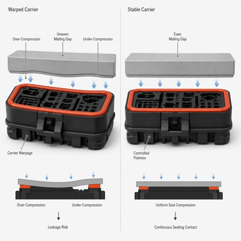
LSR overmolded connector face seals can leak even when the silicone profile looks visually complete if the rigid plastic carrier is warped, bowed or tilted. Carrier deformation changes the mating gap around the perimeter, causing some areas of the silicone seal to be over-compressed while other areas receive insufficient compression. Reliable waterproof performance therefore depends on both the LSR seal geometry and the dimensional stability of the rigid plastic structure beneath it.
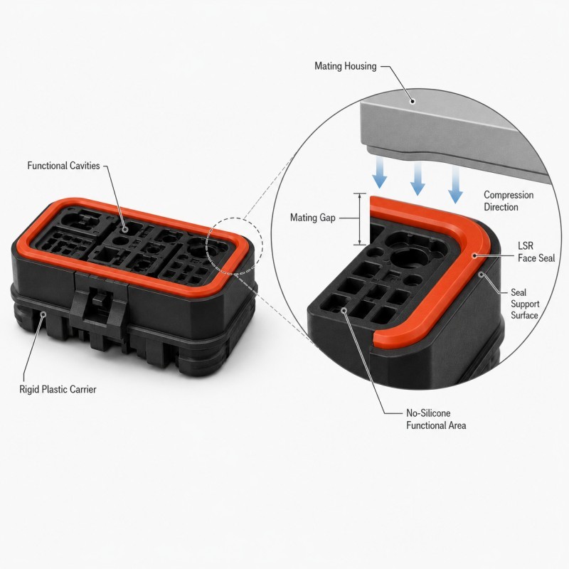
A connector face seal does not work independently from the plastic carrier.
The rigid connector body determines the location, flatness and support of the silicone sealing path.
The LSR provides the compliant contact needed to close the leakage path after the connector is assembled with its mating component.
If the plastic carrier remains flat and correctly positioned, the seal can compress relatively consistently around the perimeter.
If the carrier bends or twists, the nominal silicone profile may still look correct when the part is inspected separately, but the final assembly gap can vary from one side to another.
This is why a connector can pass visual inspection and still fail a waterproof test.
For a broader review of this failure mechanism, see how plastic insert deformation affects LSR overmolding quality.
How Does Plastic Carrier Warpage Change Seal Compression?
A perimeter seal is designed around an expected mating gap.
When the rigid carrier is flat, this gap can remain relatively consistent around the sealing path.
Warpage changes that condition.
One side of the connector may move closer to the mating housing while the opposite side moves farther away.
The result can include:
• Excessive compression on one edge
• Insufficient compression on the opposite edge
• Uneven corner contact
• Local silicone bulging
• Increased assembly force
• A low-pressure leakage path
• Different results between nominally identical parts
The problem may be very small dimensionally but still significant functionally.
A flexible LSR seal can compensate for a certain amount of variation, but it cannot correct unlimited rigid-part deformation.
The correct engineering target is therefore not simply to make the silicone softer or taller.
The plastic carrier and silicone profile must stay within a compatible dimensional window.
Why Can the Plastic Carrier Warp During LSR Overmolding?
Plastic carrier deformation can begin before, during or after the LSR overmolding process.
Possible causes include:
• Uneven plastic wall thickness
• Residual molding stress
• Weak ribs or unsupported walls
• Insert tolerance
• Mold clamping pressure
• Heated LSR tooling
• Silicone injection pressure
• Uneven cooling
• Poor insert support
• Handling after demolding
A carrier can look acceptable after the first plastic injection process and still change shape when it enters a heated LSR mold.
Thin walls and large unsupported surfaces are particularly sensitive because they have less structural resistance to heat and pressure.
The risk is also higher when the silicone flow applies force to one side of the plastic insert.
For this reason, the rigid carrier should be treated as part of the LSR system rather than as a finished independent plastic component.
Why Are Perimeter Face Seals Sensitive to Carrier Flatness?
A connector face seal often surrounds a relatively large functional opening or group of cavities.
This means the sealing path can extend across several sides and multiple corners.
If the rigid carrier bows slightly, the dimensional error is not limited to one point.
It can influence an entire side of the perimeter.
A long sealing path may therefore show:
• Different compression from side to side
• Corner-to-straight-section variation
• Uneven visible seal height
• Local over-compression near a rigid support
• Under-compression near a flexible wall
Silicone wall thickness also affects how much local deformation the seal can accommodate.
A very thin seal may have limited compliance, while an unnecessarily large section may become unstable or increase assembly force.
The correct cross-section should therefore be reviewed together with carrier flatness.
For related geometry guidance, review how wall thickness should be designed for LSR overmolding.
How Should the Plastic Carrier Be Supported During Molding?
The plastic carrier should be supported from stable rigid features while LSR is injected around the sealing area.
Support should resist the forces that can move, tilt or bow the connector body.
Important review points include:
• Insert locating datums
• Mold support surfaces
• Clamping areas
• Silicone flow direction
• Gate position
• Large unsupported walls
• Thin connector walls
• Functional cavities that must not be distorted
A support feature should not damage the connector or block a required silicone area.
At the same time, locating the carrier only at distant weak points can allow the sealing face to move during injection.
For precision connector parts, the mold should control the relationship between the plastic functional cavities and the perimeter LSR seal.
This is especially important when the final waterproof performance depends on the seal remaining parallel to the mating housing.
For related DFM guidance, review how insert positioning affects custom LSR overmolding quality.
How Do Plastic Wall Thickness and Ribs Affect Seal Flatness?
The geometry of the rigid plastic carrier affects how well the sealing face maintains its shape.
High-risk plastic structures may include:
• Large flat unsupported surfaces
• Very thin perimeter walls
• Abrupt wall-thickness changes
• Weak corners
• Long narrow sections
• Unbalanced rib layouts
Adding more plastic everywhere is not automatically the correct solution.
Excessive thickness can create its own injection-molding problems, including shrinkage and residual stress.
Ribs and local supports should reinforce the regions that control sealing geometry without creating unnecessary thickness variation.
The goal is to maintain the dimensional relationship between the connector cavities, the LSR sealing path and the final mating surface.
This structure should be reviewed before both the plastic mold and the LSR overmolding tool are finalized.
Why Should Final Seal Compression Be Defined From the Rigid Assembly?
Seal compression should be defined from the real assembled geometry.
The final condition can be affected by:
• Plastic carrier flatness
• Mating housing flatness
• LSR seal height
• Assembly stop position
• Connector alignment
• Housing tolerance
• Local plastic deformation
If the design only specifies silicone height without defining the rigid closing condition, the actual compression can vary significantly.
One part may be highly compressed while another part with the same silicone dimension receives much less contact pressure.
Where possible, rigid assembly geometry should limit the final closing position so that the silicone remains inside its intended compression range.
This also helps prevent the common reaction of increasing assembly force to compensate for an unstable seal.
For detailed guidance, review how compression stops should be designed for LSR overmolded seals.
Why Is Measuring Seal Height Alone Not Enough?
Seal height is an important dimension, but it does not describe the complete waterproof interface.
A finished connector can have an acceptable silicone height and still have a warped carrier.
Useful inspection may therefore include:
• Seal height
• Seal width
• Carrier flatness
• Reference-plane position
• Connector-body distortion
• Seal-to-cavity position
• Corner height
• Final assembly gap
The inspection plan should identify which rigid datum controls the waterproof interface.
If the measurement references a surface that moves with the warped carrier, the inspection result may hide the real problem.
For critical sealing structures, engineers should compare the plastic insert before LSR molding, the finished overmolded component and the final assembled condition.
This makes it easier to determine whether variation comes from the plastic carrier, the silicone molding step or the mating assembly.
Connector Face Seal Warpage DFM Checklist
| DFM Item | What Engineers Should Confirm | Main Risk |
Carrier flatness | Sealing face remains within required geometry | Uneven compression |
Plastic wall thickness | Walls are stable through LSR processing | Warpage |
Rib support | Critical face areas have adequate support | Local bending |
Functional cavities | Cavities remain dimensionally stable | Mating interference |
LSR seal height | Seal matches real assembly gap | Under/over-compression |
Seal width | Cross-section remains stable around perimeter | Local sealing variation |
Insert datum | Connector is located from rigid features | Tilt or offset |
Mold support | Carrier cannot bow during LSR injection | Face distortion |
| Silicone flow | Flow does not push weak plastic walls | Insert movement |
| Assembly stop | Final closing position is controlled | Compression variation |
| Validation | Flatness, assembly and leak testing are defined | Visually good part leaks |
The silicone mold design and tooling review should confirm the connector datum, carrier support, perimeter seal geometry, mold shut-off, parting line, gate, venting and final assembly compression before mold steel is finalized.
How Should Carrier Warpage and Seal Compression Be Validated?
Validation should check the rigid plastic structure and the LSR seal as one system.
Recommended validation includes:
1. Plastic Carrier Inspection
Measure key dimensions and sealing-face flatness before LSR overmolding where required.
2. Post-Molding Flatness Inspection
Confirm that the LSR process has not introduced unacceptable bowing, twisting or dimensional change.
3. Seal Geometry Inspection
Measure critical seal height, width, boundary position and corner consistency.
4. Assembly Fit Check
Assemble the connector with the real or representative mating component and check alignment and closing condition.
5. Compression Review
Confirm that the LSR seal remains continuously engaged around the full perimeter.
6. Leak Testing
Perform the agreed air-leak, pressure-decay, immersion or other waterproof test in the final assembled condition.
7. Minimum and Maximum Tolerance Evaluation
Compare representative dimensional extremes rather than nominal parts only.
8. Environmental Conditioning
Where required, repeat dimensional and leak testing after the defined thermal, vibration or humidity conditions.
9. Pilot-Production Review
Compare multiple mold cavities, consecutive molding cycles and realistic incoming plastic lots before mass-production approval.
Flatness limits, compression targets and leak criteria should always come from the actual connector assembly and customer validation requirements.
How SiliconePlus Supports Connector Seal DFM
SiliconePlus supports custom connector and silicone-over-plastic LSR overmolding projects from structural review through tooling, sampling, inspection and mass production.
Project support can include:
• Plastic connector carrier DFM
• LSR perimeter-seal review
• Carrier flatness and wall-thickness review
• Insert-positioning analysis
• Mold-support design
• Seal compression and tolerance review
• Mold shut-off and parting-line analysis
• Gate and venting review
• Precision mold development
• LSR injection molding
• Dimensional and appearance inspection
• Assembly and waterproof test support
• Pilot-production validation
Specific plastic material, carrier geometry, seal dimensions, compression conditions and waterproof acceptance criteria should always be confirmed according to the actual connector and mating assembly.
FAQ
Can an LSR Connector Seal Leak Even If the Silicone Looks Perfect?
Yes. A warped or tilted plastic carrier can change the final mating gap even when the silicone profile itself appears complete.
Can Softer Silicone Compensate for Plastic Carrier Warpage?
Only to a limited extent. Softer LSR can conform more easily, but it cannot correct unlimited rigid-part distortion or a severely uneven assembly gap.
Why Does Only One Side of the Connector Leak?
Possible causes include carrier bowing, insert tilt, uneven seal height, mating-housing variation or asymmetric support.
Should Carrier Flatness Be Checked Before LSR Overmolding?
For critical waterproof components, checking the plastic insert before and after overmolding can help identify where dimensional change occurs.
Can a Taller Seal Solve Under-Compression?
Not automatically. Increasing seal height can create over-compression elsewhere if the rigid carrier is not flat.
Should Waterproof Testing Be Done on the Loose Connector Part?
No. Functional leak testing should be completed in the actual or representative mating assembly because sealing depends on the final compression condition.
Conclusion
Connector leakage is not always a silicone-material problem.
An LSR face seal can only perform consistently when the rigid plastic carrier keeps the sealing path in the intended position.
Reliable design requires coordinated control of:
• Plastic carrier flatness
• Wall thickness and structural support
• Insert positioning
• LSR seal geometry
• Assembly compression
• Rigid seating condition
• Mating-part alignment
• Dimensional inspection
• Waterproof validation
The most effective approach is to review the rigid carrier and flexible LSR seal as one sealing system during DFM.
If carrier warpage is discovered only after the first waterproof failure, changing silicone hardness or increasing seal height may treat the symptom without correcting the real cause.
Developing an LSR Overmolded Waterproof Connector?
If you are developing an automotive, electronic or industrial connector with an integrated LSR face seal, send your connector drawing, plastic material, sealing geometry, mating-part drawing, waterproof requirements and estimated quantity to the SiliconePlus engineering team for a project-specific DFM review.