Why Do LSR Overmolded Buttons Feel Too Hard, Too Soft, or Inconsistent?
Introduction
An LSR overmolded button may look correct, seal correctly, and fit inside the housing, but still create an unacceptable user experience.
Common complaints include:
- The button feels too hard
- The button feels too soft
- The user cannot feel a clear response
- The button travels too far
- The button activates before it visibly moves
- The button reaches the end of its travel without activating the switch
- One side feels different from the other
- The button rebounds slowly
- The button remains partially pressed
- Actuation force changes after assembly
- Actuation force changes after temperature testing
- Different mold cavities produce different button feel
- Engineering samples feel correct but mass-production parts do not
These problems are often attributed to silicone hardness.
However, button performance depends on the complete mechanical system:
- Silicone material
- Shore A hardness
- Button diameter
- Button height
- Dome or web geometry
- Membrane thickness
- Travel distance
- Return force
- Switch height
- Switch position
- Housing clearance
- Assembly preload
- Sealing compression
- Insert position
- Parting-line flash
- Product temperature
- Repeated pressing
- Measurement method
A button can use the correct silicone hardness and still feel wrong when the switch is positioned too high, the housing compresses the silicone before use, or the button center does not align with the internal switch.
For engineers, sourcing teams and OEM buyers, the correct question is not only:
“What Shore A hardness should the button use?”
The more useful question is:
“What force, travel, feedback, return and assembly behavior should the complete button system provide?”
This guide explains how LSR overmolded button force and tactile performance should be designed, measured and validated before mass production.
Answer Excerpt
LSR overmolded buttons can feel too hard, too soft or inconsistent when silicone hardness, dome geometry, membrane thickness, travel distance, assembly preload, switch height, housing clearance and button alignment are not properly coordinated.
A button may feel correct as a separate molded component but become harder after installation because the housing pre-compresses the silicone or reduces the available travel.
For designs in which the silicone structure generates tactile feedback, actuation force, drop force, snap ratio, return force and travel should be defined. For designs that press an internal tactile switch or metal dome, the complete assembled force-displacement curve should be measured.
Reliable performance requires the silicone button, plastic or metal housing, FPC, switch, assembly stack, waterproof structure and test method to be treated as one complete system.
1. First Identify the Button Architecture
Not every LSR overmolded button works in the same way.
Before discussing force or tactile feedback, engineers should identify where the button response comes from.
Silicone Membrane or Dome Provides the Tactile Response
In this structure, a shaped silicone web or dome collapses when pressed and then returns to its original position.
The silicone geometry directly controls:
- Actuation force
- Snap feeling
- Travel
- Return force
- Rebound
- Fatigue performance
Silicone Cover Presses an Internal Tactile Switch
In this structure, the internal metal dome, tact switch or microswitch provides most of the clicking feedback.
The silicone component mainly provides:
- Waterproof sealing
- Dust protection
- Soft touch
- External shape
- Force transfer
- Switch protection
The final button feel depends on both the silicone cover and the internal switch.
Silicone Plunger Transfers Force to an FPC or PCB Switch
This structure may use a molded silicone plunger, plastic carrier, FPC contact, dome switch or conductive contact beneath the button.
Small tolerance changes in the plunger height, FPC location or housing stack can change the final actuation behavior.
The measurement and design method must match the actual architecture.
Snap ratio is not automatically the correct specification for every overmolded button.
2. What Is Button Actuation Force?
Actuation force is the force required to move the button to the point where the intended switching action occurs.
Depending on the design, this may mean:
- Collapsing a silicone dome
- Activating a metal dome
- Closing a conductive contact
- Pressing a tact switch
- Moving a plunger to a defined position
- Reaching a specified electrical signal
Actuation force should not be judged only by pressing the product with a finger.
Human perception varies according to:
- Finger position
- Pressing speed
- Button size
- User strength
- Gloves
- Product orientation
- Previous button experience
- Ambient temperature
A force-displacement test provides more useful data.
Industry silicone-keypad design guides commonly specify actuation force together with snap ratio, minimum return force, stroke and expected life rather than treating button feel as one subjective description.
3. Button Travel Must Match the Switching Point
Button travel is the distance the button moves during pressing.
Travel can be divided into several functional stages:
- Initial free movement
- Silicone deformation
- Switch contact or dome collapse
- Additional overtravel
- Full mechanical stop
If the available travel is too short:
- The internal switch may not activate reliably
- Housing tolerance may prevent full contact
- The button may feel hard
- The user may need to press at a specific angle
- Temperature or assembly variation may cause intermittent operation
If the available travel is too long:
- The button may feel loose
- The silicone may stretch excessively
- The user may not receive a clear response
- The internal switch may be overloaded
- The button may bottom out against the housing
- Rebound may become unstable
The intended electrical switching point should occur within a controlled mechanical travel window.
4. Snap Ratio Affects Tactile Feedback
For silicone structures that create their own tactile response, snap ratio describes the reduction in force after the peak actuation force is reached.
A common expression is:
Snap Ratio = (Peak Actuation Force − Contact Force) ÷ Peak Actuation Force × 100%
A greater force drop usually creates a more noticeable tactile event.
A smaller force drop creates a softer or less distinct response.
However, a high snap ratio is not automatically better.
The appropriate response depends on:
- Button purpose
- User expectation
- Required life
- Button size
- Pressing frequency
- Glove use
- Product environment
- Internal switch architecture
- Noise requirements
Some medical, wearable or beauty-device interfaces may need a smooth, quiet response.
Industrial or automotive controls may require clearer confirmation, especially when the user wears gloves.
For buttons in which an internal metal dome provides the click, engineers should evaluate the combined force curve rather than assigning the tactile response entirely to the silicone.
5. Return Force Controls Rebound
Return force is the force that moves the button back toward its original position after the user releases it.
Insufficient return force can cause:
- Slow rebound
- Partial sticking
- Incomplete switch release
- Repeated electrical activation
- Button height variation
- Poor user confidence
- Dust or liquid collecting around a depressed button
Excessive return force may:
- Increase actuation force
- Make the button feel stiff
- Increase stress at the bonding edge
- Increase load on the housing
- Reduce comfort during repeated use
Return force depends on:
- Dome or web geometry
- Silicone hardness
- Membrane thickness
- Button travel
- Assembly preload
- Temperature
- Aging
- Friction
- Switch return force
The button should be tested through both the pressing and return portions of the force-displacement curve.
6. Silicone Hardness Changes Force—but Does Not Define It Alone
Harder silicone generally resists deformation more strongly than softer silicone.
However, button force cannot be predicted from Shore A hardness alone.
The same hardness may produce different results when the button has different:
- Membrane thickness
- Dome angle
- Dome diameter
- Travel
- Button height
- Support structure
- Preload
- Contact area
A thin membrane made from a firmer material may still feel lighter than a thick membrane made from softer silicone.
SiliconePlus’s hardness guide also emphasizes that hardness must be evaluated together with wall thickness, function, assembly force, substrate and structural requirements.
If the Silicone Is Too Soft
Possible problems include:
- Weak tactile response
- Excessive travel
- Slow rebound
- Button collapse
- Accidental activation
- Edge rolling
- Shape instability
- Greater sensitivity to assembly compression
If the Silicone Is Too Firm
Possible problems include:
- High actuation force
- Reduced comfort
- Limited travel
- Switch overloading
- Greater bonding-edge stress
- Difficult demolding
- Incomplete contact under tolerance variation
The final material should be validated through molded and assembled samples.
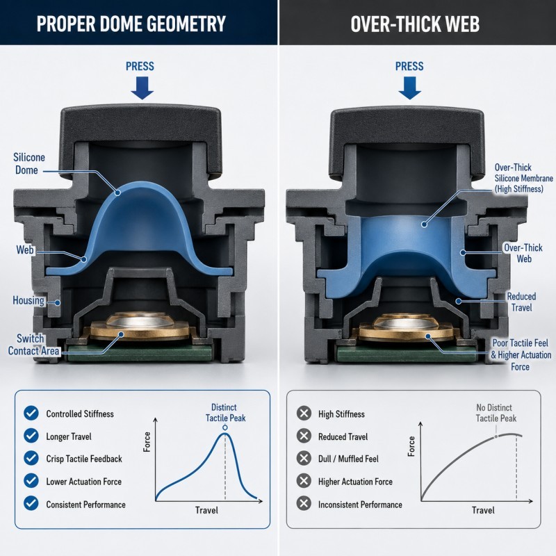
7. Dome and Web Geometry Control the Force Curve
A silicone dome or web may use:
- Conical geometry
- Curved geometry
- Bell geometry
- Flat membrane
- Double-wall structure
- Multi-stage structure
- Custom asymmetric structure
The geometry influences:
- Initial stiffness
- Peak force
- Force drop
- Travel
- Return force
- Side stability
- Fatigue performance
Important dimensions include:
- Web thickness
- Web angle
- Web length
- Dome height
- Dome diameter
- Root radius
- Center thickness
- Support-ring diameter
Small geometry changes can produce noticeable differences in button feel.
For this reason, the force target should be defined before final mold machining rather than adjusted only by changing silicone hardness after sampling.
Button geometry, force targets, switch location and assembly tolerance should therefore be reviewed during the DFM process before final tooling.
8. Uneven Membrane Thickness Creates Inconsistent Feel
A button may appear symmetrical externally but have uneven silicone thickness around its dome or web.
Possible causes include:
- Insert offset
- Core offset
- Mold-cavity variation
- Uneven flow
- Local flash
- Tool wear
- Plastic warpage
- FPC displacement
- Shrinkage differences
When one side is thinner, the button may:
- Tilt during pressing
- Activate from one side more easily
- Feel soft in one direction
- Rub against the housing
- Recover unevenly
- Develop local whitening or fatigue
Thickness consistency should be checked around the complete button circumference.
Depending on the structure, inspection may require:
- Optical measurement
- Section analysis
- Product weight comparison
- Cavity comparison
- Force-displacement testing
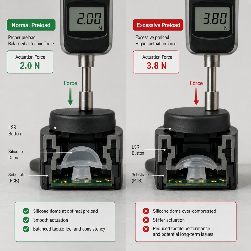
9. Assembly Preload Can Make the Button Feel Harder
Preload is the compression already applied to the button before the user presses it.
Preload may come from:
- Housing assembly
- Screws
- Snap-fit structures
- Cover plates
- Switch height
- FPC stack thickness
- Adhesive layers
- Sealing compression
- Plastic warpage
- Tolerance stack-up
A small intended preload can help remove looseness.
Excessive preload can:
- Raise the initial force
- Reduce available travel
- Keep the internal switch partially pressed
- Slow rebound
- Distort the silicone dome
- Change the waterproof sealing condition
- Produce cavity-to-cavity differences after assembly
Testing the loose button alone will not reveal assembly-preload problems.
The complete product stack must be measured.
10. Insufficient Preload Can Create a Loose or Unstable Button
Too little preload may leave a gap between:
- Silicone plunger and switch
- Button cap and silicone dome
- Silicone membrane and housing
- Internal actuator and FPC contact
Possible symptoms include:
- Initial dead travel
- Rattling
- Delayed switch response
- Different response depending on pressing angle
- Weak tactile feedback
- Button cap movement
- Poor dust sealing
The correct preload should remove unnecessary clearance without pre-activating the switch or over-compressing the silicone.
This balance depends on the complete assembly tolerance.
11. Switch Height and Button Height Must Be Coordinated
A height difference of only a small amount can significantly change button feel in a compact electronic assembly.
If the internal switch is too high:
- Preload increases
- Travel decreases
- Actuation force may rise
- The switch may remain partially activated
- The button may appear lower than intended
If the switch is too low:
- Dead travel increases
- The button may not activate
- The user may need to press deeply
- The silicone may bottom out elsewhere
- Side pressing may become unreliable
Critical height dimensions may include:
- Housing reference surface
- Switch top height
- FPC thickness
- Adhesive thickness
- Silicone plunger height
- Button external height
- Mechanical-stop height
- Cover thickness
These dimensions should be reviewed as a tolerance chain rather than separately.
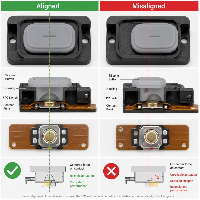
12. Switch Alignment Affects Pressing Stability
The button center should transfer force to the intended switch location.
Misalignment may occur because of:
- Insert positioning
- FPC movement
- Plastic housing tolerance
- Switch-placement tolerance
- Silicone shrinkage
- Mold-cavity variation
- Assembly error
- Warped substrates
An off-center switch can cause:
- One-sided activation
- Button tilting
- Higher force
- Inconsistent tactile feedback
- Housing rubbing
- Partial contact
- Faster local wear
Large rectangular or elongated buttons are particularly sensitive to off-center force.
The design may require:
- A wider actuator
- Multiple support points
- Guide ribs
- A rigid keycap
- Stabilizing features
- Controlled switch location
- Multiple switches
13. Long or Wide Buttons Can Wobble
A small circular button usually transfers load near its center.
A long button may be pressed at:
- The center
- The left edge
- The right edge
- A corner
- An unintended side position
If the structure does not distribute force, the button may:
- Rock
- Wobble
- Jam
- Activate only from one side
- Rub against the bezel
- Produce different force readings by position
Silicone-keypad design guidance also identifies elongated keys as more sensitive to wobbling and jamming and recommends additional stabilization when the key area is much larger than the contact area.
Testing should therefore include multiple pressing locations, not only the geometric center.
14. Housing Clearance Affects Friction
A silicone button normally moves through or against an opening in the product housing.
If the clearance is too small:
- The silicone may rub
- Actuation force may increase
- Rebound may slow
- Surface abrasion may occur
- Temperature expansion may cause sticking
- Flash may interfere with movement
If the clearance is too large:
- The button may wobble
- Dust may enter
- The appearance gap may become inconsistent
- Water-sealing requirements may become harder to achieve
- The user may press the button at an angle
The clearance must account for:
- Silicone dimensions
- Housing dimensions
- Parting-line flash
- Assembly position
- Temperature
- Button travel
- Cosmetic requirements
15. Waterproof Sealing Can Conflict With Button Feel
A waterproof button may use:
- A bonded silicone perimeter
- A compression sealing lip
- A membrane
- A wraparound seal
- An integrated housing cover
- A closed dome
Increasing sealing compression may improve contact at the waterproof interface, but it can also:
- Increase button preload
- Raise actuation force
- Reduce travel
- Slow rebound
- Distort the dome
- Move the switch relationship
Reducing compression may improve the button feel but weaken waterproof contact.
The design must balance:
- Sealing compression
- Button travel
- Actuation force
- Return force
- Housing tolerance
- Assembly force
- Environmental reliability
Waterproof performance must be tested after repeated pressing because the button is a moving sealing interface, not a static gasket.
16. Internal Air Must Move During Pressing
A closed silicone button cavity may contain trapped air.
When the button is pressed, the internal volume changes.
If the air cannot move appropriately, it may create:
- Pneumatic resistance
- Slow actuation
- Slow rebound
- Temperature-sensitive force
- A soft “air cushion” feeling
- Pressure buildup
- Membrane deformation
Possible design strategies include:
- Controlled air channels
- Internal vent paths
- Shared cavity volume
- Suitable membrane geometry
- Avoiding completely trapped pockets
Any air path must be coordinated with waterproof and dustproof requirements.
An uncontrolled opening may improve button feel but create a leakage route.
17. Parting-Line Flash Can Interfere With Movement
Flash may appear around:
- Button perimeter
- Membrane edge
- Moving wall
- Housing-contact surface
- Plunger
- Sealing lip
- Dome root
Even thin flash can:
- Rub against the housing
- Increase actuation force
- Slow rebound
- Create an uneven appearance
- Tear during repeated pressing
- Affect the waterproof interface
SiliconePlus’s flash-control guide specifically identifies flash around button movement areas as a risk to tactile feel, rebound and movement.
The drawing should define which button edges are critical to movement and sealing.
Critical button edges should be reviewed together with flash and tolerance control before sample approval.
18. Insert Positioning Changes the Button Geometry
An LSR overmolded button may be molded onto:
- Plastic housing
- Metal frame
- FPC
- Connector cover
- Electronic module
- Pre-molded carrier
If the insert shifts inside the mold, it can change:
- Button height
- Silicone thickness
- Dome symmetry
- Plunger position
- Housing clearance
- Bonding-edge width
- Sealing-lip position
A small insert offset may therefore become a noticeable force difference.
Insert-positioning fixtures should maintain the substrate at the correct height, angle and lateral position throughout injection and curing.
Stable insert positioning is required to maintain repeatable button height, silicone thickness, switch alignment and sealing position.
19. Plastic Warpage Can Change the Final Button Feel
The plastic housing or carrier may warp before, during or after LSR overmolding.
Warpage can change:
- Switch-to-button distance
- Perimeter sealing compression
- Button angle
- Housing clearance
- Assembly preload
- Left-right button force
Possible causes include:
- Plastic molding stress
- Uneven wall thickness
- LSR mold temperature
- Unsupported areas
- Storage deformation
- Screw torque
- Final product assembly
The plastic insert should be measured before overmolding and again in the final assembly.
A silicone material change cannot correct an unstable plastic reference surface.
20. FPC Position and Adhesive Thickness Affect the Switching Point
In compact electronic products, the internal switch may be mounted on FPC.
The switching position may change because of:
- FPC thickness
- Stiffener thickness
- Adhesive thickness
- Dome placement
- FPC bowing
- Assembly pressure
- Connector tension
- Component placement tolerance
An FPC may also flex when the button is pressed.
This movement can absorb part of the intended travel and change the force curve.
The FPC should have suitable support beneath the switching area.
The overmolded button, FPC, adhesive and support structure should be tested as a complete assembly.
21. Temperature Changes Button Force and Rebound
Silicone, plastic, adhesive, FPC and internal switches do not respond identically to temperature.
At different temperatures, the complete button may show changes in:
- Material flexibility
- Housing dimensions
- Switch force
- Preload
- Friction
- Return speed
- Travel
- Sealing compression
A button that feels acceptable at room temperature may become harder, softer or slower under the actual operating conditions.
Validation may need to include:
- Low-temperature pressing
- High-temperature pressing
- Temperature recovery
- Thermal cycling
- Humidity exposure
- Repeated pressing after conditioning
The force target should specify the measurement temperature when environmental performance is important.
22. Repeated Pressing Can Change the Force Curve
A button may meet the initial force requirement but change after repeated operation.
Possible changes include:
- Reduced peak force
- Reduced tactile response
- Slower rebound
- Permanent dome deformation
- Increased dead travel
- Cracking around the web
- Bonding-edge fatigue
- Switch wear
- Housing wear
- Friction changes
The durability test should evaluate more than whether the electrical switch still functions.
Depending on the project, engineers may need to compare:
- Initial force curve
- Intermediate force curve
- Final force curve
- Button height
- Return time
- Appearance
- Waterproof performance
- Electrical response
The number of cycles should come from the actual application requirement rather than a universal marketing claim.
23. Measurement Speed Changes the Result
Silicone is a viscoelastic material, so force readings can vary with the pressing method.
Results may change according to:
- Pressing speed
- Probe shape
- Probe position
- Product support
- Measurement temperature
- Hold time
- Return speed
- Number of preconditioning presses
A fast test may produce a different peak force from a slow test.
A narrow probe may produce a different result from a fingertip-shaped probe.
The test plan should define:
- Test equipment
- Probe diameter or shape
- Pressing location
- Pressing speed
- Maximum travel
- Product fixture
- Number of conditioning cycles
- Temperature
- Data points to record
Without a defined method, two laboratories may report different results for the same button.
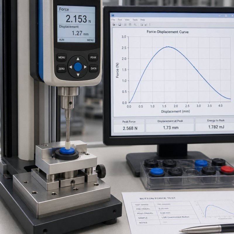
24. Test the Complete Force-Displacement Curve
A single peak-force value cannot describe the complete user experience.
A force-displacement curve may reveal:
- Initial preload
- Free travel
- Rising force
- Peak actuation force
- Force drop
- Contact point
- Overtravel
- Mechanical stop
- Return force
- Hysteresis
- Incomplete recovery
Two buttons may have the same peak force but feel different because one has:
- More dead travel
- A sharper force drop
- Lower return force
- Greater overtravel
- More friction
The buyer and manufacturer should agree which portions of the curve are functionally important.
25. Why Can Samples Feel Correct but Mass Production Become Inconsistent?
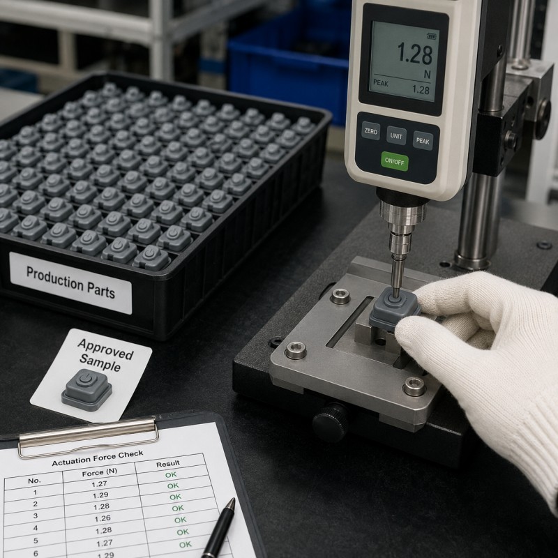
Engineering samples are normally produced and assembled under close supervision.
During sampling:
- Inserts may be selected carefully
- One mold cavity may receive more attention
- Switches may come from one batch
- Assembly is performed slowly
- Housing parts may be matched manually
- Engineers may adjust the process after every trial
Mass production introduces:
- Multiple cavities
- Different silicone batches
- Different switch batches
- Plastic-housing variation
- FPC variation
- Adhesive-thickness variation
- Operator changes
- Assembly-speed changes
- Mold-temperature drift
- Tool wear
- Flash buildup
- Screw-torque variation
A button structure with little tolerance margin may pass several samples but become unstable during normal production variation.
Pilot production should compare:
- Every mold cavity
- Different plastic batches
- Different switch or FPC batches
- Beginning and end of the run
- Force-displacement curves
- Assembly preload
- Return performance
- Waterproof performance
26. A Practical Button-Failure Analysis
When an LSR overmolded button feels too hard, soft or inconsistent, investigate the problem systematically.
Recommended sequence:
- Define the exact complaint.
- Confirm whether the problem exists before or after assembly.
- Measure the loose molded button.
- Measure the complete assembly.
- Record the force-displacement curve.
- Identify the switch architecture.
- Measure switch height and switching force.
- Measure silicone button height and travel.
- Check housing clearance.
- Check assembly preload.
- Inspect dome or membrane thickness.
- Check button-to-switch alignment.
- Compare mold cavities.
- Compare plastic, FPC and switch batches.
- Inspect flash around moving areas.
- Review screw torque and assembly sequence.
- Test at the required temperatures.
- Compare initial and aged samples.
- Change one controlled variable.
- Repeat the force and functional test.
Do not change silicone hardness, dome thickness, switch height, housing clearance and assembly preload simultaneously.
Changing one controlled variable at a time makes the actual root cause easier to confirm.
27. What Should Be Validated Before Mass Production?
Before approving a custom LSR overmolded button, buyers and manufacturers should confirm:
- Button architecture
- Silicone material
- Shore A hardness
- Button diameter
- Button height
- Dome or web geometry
- Membrane thickness
- Root radius
- Intended travel
- Actuation-force range
- Return-force requirement
- Snap-ratio requirement, when applicable
- Internal switch type
- Switch-force specification
- Switch height
- FPC or PCB position
- Plunger position
- Housing clearance
- Assembly preload
- Mechanical-stop position
- Waterproof sealing structure
- Air path or internal cavity
- Insert position
- Parting-line location
- Flash standard
- Measurement equipment
- Probe position
- Test speed
- Test temperature
- Pressing-life requirement
- Environmental conditioning
- Assembly torque
- Pilot-production results
- Cavity traceability
- Final reference sample
Approval should cover both the mechanical feel and the electrical function.
A button that feels correct but activates unreliably is not acceptable.
A button that activates reliably but is too hard, slow or unstable may also fail the product requirement.
How SiliconePlus Supports LSR Button Force and Tactile Development
SiliconePlus provides custom liquid silicone injection molding and silicone overmolding services for buttons and electronic interface components used in:
- Automotive electronics
- 3C electronics
- Wearable devices
- Medical equipment
- Beauty devices
- Sensors
- Industrial controls
- Waterproof handheld products
Our project support can include:
- DFM and drawing review
- Button-architecture evaluation
- Silicone material and hardness selection
- Dome, web and membrane review
- Travel and preload review
- Switch-alignment evaluation
- Housing-tolerance review
- Waterproof sealing review
- Silicone over plastic
- Silicone over metal
- FPC silicone overmolding
- Custom mold development
- Sample and pilot production
- Force-displacement testing coordination
- Appearance and dimensional inspection
- Waterproof testing coordination
- Repeated-pressing validation support
- OEM/ODM mass production
With 25+ years of silicone manufacturing experience, our team evaluates the complete relationship between:
- Silicone button
- Substrate
- Housing
- FPC or PCB
- Internal switch
- Assembly stack
- Waterproof interface
- Force and travel requirement
The objective is not only to produce a soft external button.
The objective is to achieve repeatable actuation force, controlled travel, reliable switching, stable rebound and waterproof performance throughout mass production.
What Information Should Buyers Send for Evaluation?
To evaluate an LSR overmolded button project, buyers should provide:
- 2D drawing
- 3D file
- Product photographs
- Physical sample, when available
- Button architecture
- Substrate material
- Silicone material requirement
- Hardness preference
- Button dimensions
- Intended actuation force
- Intended travel
- Return-force requirement
- Internal switch model
- Switch-force data
- Switch height
- FPC or PCB drawing
- Housing drawing
- Assembly stack
- Waterproof requirement
- Pressing-life requirement
- Operating-temperature range
- Force-test method
- Known failure information
- Estimated quantity
- Target production schedule
When an existing product has an inconsistent button-feel problem, buyers should also provide:
- Force-displacement reports
- Pressing videos
- Passing and failing samples
- Mold-cavity numbers
- Plastic or FPC batches
- Switch batches
- Assembly torque
- Environmental-test records
Frequently Asked Questions
Why does the button feel correct before assembly but too hard afterward?
The housing, switch or cover may pre-compress the silicone, reduce available travel or increase friction around the button.
Does softer LSR always reduce actuation force?
No. Geometry, wall thickness, preload, switch force and housing clearance also affect the result. Softer material may create longer travel or weaker rebound without reducing the complete assembled force appropriately.
Why does the button have no clear click?
The design may have a low force drop, excessive preload, insufficient travel, a soft web, an unsuitable switch or friction that hides the tactile event.
Does every silicone button need a snap-ratio specification?
No. Snap ratio is mainly relevant when the silicone structure produces the tactile response. When an internal metal dome or tact switch provides the click, the complete assembly force curve is more useful.
Why does the button rebound slowly?
Possible causes include low return force, excessive preload, housing friction, trapped air, soft or thin silicone, switch sticking, temperature or permanent deformation.
Why does one side of a long button feel harder?
The internal switch may be off-center, the key may lack stabilization, the membrane thickness may be uneven, or the button may rub against the housing.
Can increasing the dome thickness improve rebound?
It may increase stiffness and return force, but it can also increase actuation force and reduce travel. The complete force curve must be revalidated.
Can a waterproof button maintain a soft pressing feel?
It may be possible when sealing compression, dome structure, preload, travel, housing tolerance and switch force are properly balanced.
Why does one mold cavity produce harder buttons?
Possible causes include dimensional differences, membrane-thickness variation, insert position, mold temperature, flash, curing or cavity-specific tool wear.
What should buyers approve before bulk production?
Buyers should approve the material, hardness, button geometry, force curve, travel, switch position, preload, housing clearance, rebound, waterproof testing, environmental testing and pilot-production consistency.
Conclusion
An LSR overmolded button can feel too hard, too soft or inconsistent even when the silicone material meets the specified Shore A hardness.
The final user experience depends on the complete relationship between the silicone dome, membrane thickness, travel, actuation force, return force, switch height, housing clearance, assembly preload, insert position, temperature and production tolerance.
The most reliable approach is to define measurable force and travel requirements before tooling, test the complete assembled product, review the full force-displacement curve and validate multiple mold cavities and component batches during pilot production.
If you are developing an LSR overmolded button, waterproof electronic interface, FPC button module, automotive control, wearable switch or medical-device button, contact SiliconePlus and send us your drawings, switch information, button-force target, travel requirement, assembly stack, waterproof standard, environmental conditions and estimated quantity. Our engineering team will review the project and provide practical manufacturing recommendations.