Home / All / Silicone Overmolding Products / Automotive Silicone Overmolding / Custom LSR Overmolded EV Charging Inlet Terminal Seal
Custom LSR Overmolded EV Charging Inlet Terminal Seal
| Share | |
|---|---|
| Categories | Automotive Silicone Overmolding |
| Brand | SiliconePlus | Silicone OverMolding Manufacturing |
| Brand | SiliconePlus |
| Product Type | EV Charging Inlet Terminal Seal |
| Silicone Material | Liquid Silicone Rubber (LSR) |
| Insert Material | Copper Alloy / Customer-Specified Metal Terminal |
| Molding Process | LSR Overmolding / Insert Molding |
| Main Function | Waterproof Sealing / Insulation / Protection |
| Seal Structure | Integrated Silicone Sealing Collar |
| Exposed Functional Area | Electrical Mating Contact |
| Silicone Hardness | Customized According to Sealing Requirements |
| Application | EV Charging Inlet / Charging Connector |
| Custom Input | 2D Drawing / 3D File / Physical Sample |
| Service | DFM / Tooling / Sampling / OEM Mass Production |
| Download |  |
Detail Information
Product Overview
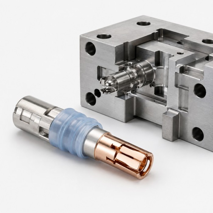
Custom LSR overmolded EV charging inlet terminal seals are developed for electric vehicle charging connectors and vehicle charging inlets that require integrated sealing, electrical protection and stable terminal positioning.
Liquid silicone rubber is molded directly around a selected section of a metal charging terminal while the electrical mating area remains completely exposed. The cured silicone can form an integrated sealing collar, interface barrier or protective zone around the terminal.
This product is not a complete EV charging inlet, charging gun or connector assembly. SiliconePlus focuses on the custom silicone overmolded sealing and protective structure manufactured according to customer drawings, terminal samples, assembly requirements and validation standards.
Project support includes DFM review, mold development, sample production, insert molding and OEM mass production through precision liquid silicone injection molding.
What Is an EV Charging Inlet Terminal Seal?
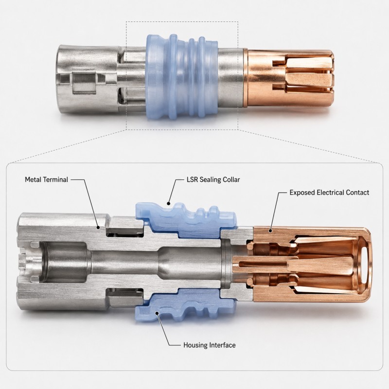
An EV charging inlet terminal seal is an integrated silicone sealing structure formed around a metal charging contact or terminal used inside an electric vehicle charging inlet or connector system.
During production, the metal terminal is positioned inside a precision LSR mold. Liquid silicone rubber is injected around the specified sealing area and cured directly around the terminal.
The electrical mating surface, conductive contact region and other specified functional areas remain exposed, while silicone covers only the section required for sealing, insulation or mechanical retention.
Compared with installing a separate O-ring or loose sealing component, an integrated silicone seal can help reduce seal displacement, missing components and assembly variation.
The overmolded silicone may provide:
• Terminal-to-housing sealing
• Moisture-ingress protection
• Dust protection
• Electrical insulation around non-contact areas
• Vibration damping
• Stable silicone positioning
• Reduced loose-seal assembly
• Customized sealing geometry
• Mechanical retention around the terminal
• Controlled interface dimensions
The complete charging inlet performance depends on the metal terminal, silicone structure, plastic housing, mating interface, assembly conditions and final system validation.
Why Use an Integrated Overmolded Seal?
EV charging interfaces must maintain reliable electrical connection while protecting critical internal areas from moisture, dust, vibration and environmental exposure.
Traditional designs may use separate O-rings, sealing mats or secondary sealing components. These methods can work effectively, but they introduce additional parts and assembly steps.
An integrated LSR overmolded terminal seal can help provide:
• Defined seal position around the terminal
• Reduced risk of missing a separate seal
• Reduced seal twisting or displacement
• Fewer loose assembly components
• Repeatable sealing geometry
• Integrated insulation around selected metal areas
• Better protection around terminal pass-through areas
• Custom sealing features for compact connector structures
• Stable positioning during repeated production
• Reduced dependence on manual seal placement
Commercial EV charging contact systems already use integrated overmolded silicone seals as one approach to protecting charging contacts, demonstrating that this is a practical connector architecture rather than only a theoretical molding concept.
However, the silicone overmold alone does not determine the waterproof rating of the complete charging inlet. Housing geometry, mating surfaces, cable interfaces, fastening, venting and final assembly must also be evaluated.
Key Design Requirements Before Tooling
Electrical Contact Area Protection
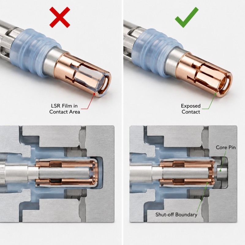
The electrical mating area of the charging terminal must remain completely clean and exposed after silicone overmolding.
This area may include:
• Mating contact surface
• Conductive contact zone
• Plated electrical surface
• Contact spring area
• Terminal insertion area
• Threaded connection
• Crimp or weld area
• Measurement point
• Locating surface
• Assembly datum
• Other customer-defined functional surfaces
Liquid silicone rubber can enter very small gaps. If the mold shut-off is unstable or the terminal position changes, a thin silicone membrane may cover part of the electrical contact.
Even a small amount of silicone contamination can affect:
• Electrical contact
• Terminal insertion
• Connector assembly
• Dimensional fit
• Contact resistance
• Inspection
• Subsequent welding or crimping
• Customer acceptance
The exposed electrical area must therefore be defined clearly before mold development.
For related design risks, review why LSR overmolding blocks holes, contact pads and connector openings.
Metal Terminal Positioning
The charging terminal must remain accurately positioned during mold loading, mold closing, silicone injection, curing and demolding.
If the terminal moves, rotates, tilts or floats during injection, the silicone seal may no longer align with the designed sealing area.
Possible problems include:
• Uneven silicone thickness
• Off-center sealing collar
• Exposed metal in the sealing area
• Silicone entering the contact area
• Flash around the terminal
• Incorrect seal height
• Assembly interference
• Unstable terminal position
• Inconsistent dimensions
• Waterproof-test variation
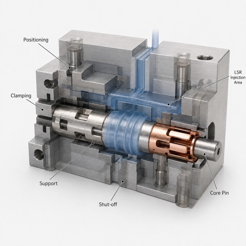
The mold may require locating pins, terminal nests, support surfaces, controlled clamping points and precision shut-off areas.
The support structure should hold the metal insert securely without damaging the functional contact surface.
Accurate insert positioning in LSR overmolding is essential for maintaining repeatable sealing geometry and mass-production stability.
Metal and Silicone Interface Design
Metal-to-silicone overmolding should be treated as a complete material, structure and process system.
The interface design should consider:
• Metal alloy
• Plating or surface treatment
• Surface cleanliness
• Silicone material
• Silicone hardness
• Bonding requirement
• Molding temperature
• Mechanical loading
• Sealing pressure
• Environmental exposure
• Thermal cycling
• Terminal dimensional tolerance
Some projects may use chemical adhesion between silicone and metal.
Other projects may use mechanical retention features such as:
• Through-holes
• Retention grooves
• Small windows
• Undercuts
• Knurled areas
• Edge wraparound
• Enlarged locking sections
• Combination chemical and mechanical retention
The correct approach depends on the actual metal terminal and customer requirements.
For additional information, review our guide to metal with silicone overmolding manufacturing.
Mechanical Retention
Mechanical retention can provide an additional physical lock between the cured silicone and the metal terminal.
This is especially useful when the interface may experience pulling, vibration, thermal cycling, repeated assembly or uncertainty in long-term chemical adhesion.
Possible locking structures include:
• Through-hole retention
• Groove retention
• Undercut retention
• Edge wraparound
• Window locking
• Rib locking
• Multi-directional locking
• Combination chemical bonding and mechanical retention
The mechanical feature should be positioned away from the functional electrical contact area.
The locking geometry must also consider silicone flow, venting, demolding direction and the minimum silicone thickness around the feature.
For projects with long-term peel or pull loading, review when LSR overmolding needs mechanical retention.
Silicone Seal Geometry
The silicone geometry should be designed according to the charging inlet housing and the final sealing interface.
Important dimensions may include:
• Seal outer diameter
• Seal height
• Compression lip height
• Silicone wall thickness
• Terminal-to-seal concentricity
• Transition radius
• Locking-section thickness
• Housing insertion clearance
• Seal compression
• Parting-line location
• Flash allowance
• Assembly tolerance
A seal that is too small may not generate enough compression.
A seal that is too large may create excessive insertion force or assembly interference.
Very thin silicone areas can be difficult to fill consistently and may tear during demolding.
Abrupt transitions between thick and thin silicone sections may also create molding and dimensional risks.
The sealing geometry should therefore be reviewed together with the terminal, plastic housing and final assembly.
Mold Shut-Off and Flash Control
The mold shut-off determines exactly where the liquid silicone stops around the metal charging terminal.
Critical shut-off areas may include:
• Electrical mating surface
• Plated contact area
• Thread
• Terminal shoulder
• Crimping area
• Welding area
• Locating diameter
• Plastic housing interface
• Inspection datum
• Customer-defined no-silicone zone
If the mold does not seal accurately around these areas, silicone flash or a thin silicone membrane may remain on the terminal.
Excessive manual trimming should not be used as the main solution for critical electrical contact surfaces.
Flash control depends on:
• Terminal dimensional tolerance
• Insert positioning
• Mold precision
• Shut-off surface design
• Injection pressure
• Silicone flow
• Venting
• Parting-line design
• Mold wear
• Production consistency
Critical electrical areas should be inspected during sampling and pilot production before the mold is approved for mass production.
Typical Applications
Custom LSR overmolded EV charging terminal seals may be developed for:
• EV vehicle charging inlets
• AC charging interfaces
• DC fast-charging interfaces
• High-voltage charging contacts
• Vehicle-side charging connectors
• Charging terminal sealing structures
• Charging contact carriers
• High-voltage connector interfaces
• Electrified vehicle power connectors
• Commercial vehicle charging interfaces
• Charging infrastructure connector components
• Other custom high-voltage terminal sealing projects
SiliconePlus focuses on the customized silicone sealing and overmolding portion rather than supplying the complete charging inlet or charging equipment.
For broader automotive connector applications, review our custom automotive connector silicone seal solutions.
For related EV and vehicle applications, review our automotive silicone customization solutions.
Customization Options
Each EV charging terminal overmolding project is customized according to the customer’s terminal, connector housing and validation requirements.
Available customization options may include:
• Metal terminal geometry
• Silicone coverage area
• Silicone material
• Silicone hardness
• Silicone color
• Seal outer diameter
• Seal height
• Compression lip geometry
• Mechanical-retention structure
• Bonding area
• Functional contact exposure
• Parting-line position
• Gate location
• Mold shut-off structure
• Flash-control requirement
• Dimensional tolerance
• Pull-force requirement
• Leak-test requirement
• Prototype tooling
• Production tooling
• Packaging method
The final design should be evaluated using the actual terminal and charging inlet assembly whenever possible.
Quality Inspection and Validation
A charging terminal seal may look acceptable after molding but still fail during connector assembly or environmental testing.
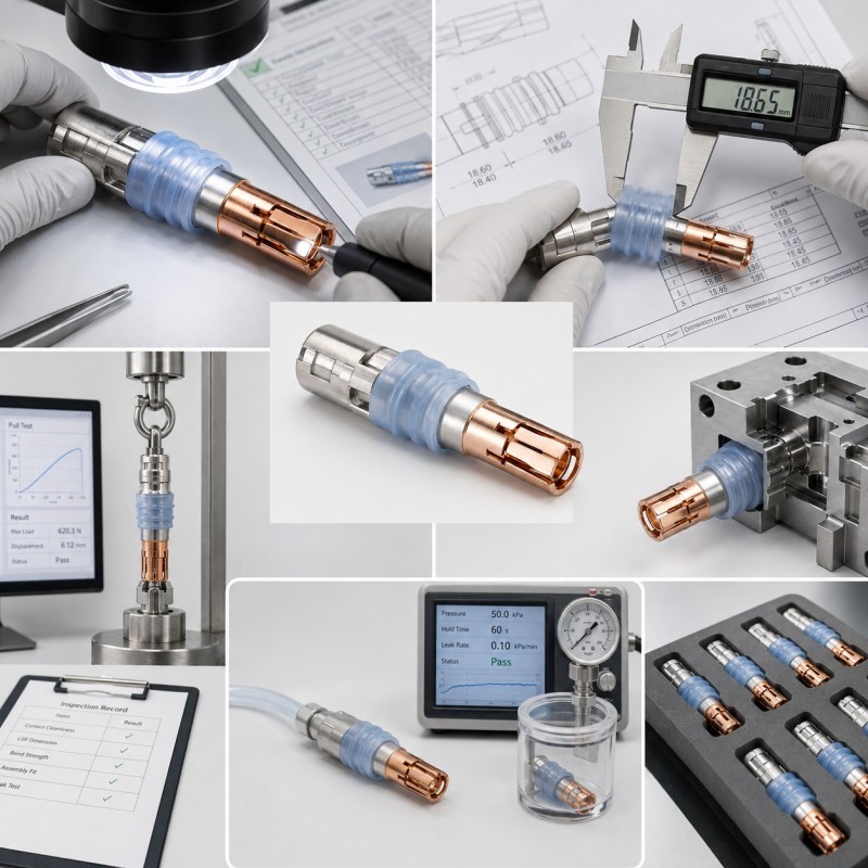
Inspection and validation may include:
• Incoming metal-terminal inspection
• Terminal-position inspection
• Silicone coverage inspection
• Electrical contact exposure inspection
• Flash inspection
• Seal outer-diameter measurement
• Seal-height measurement
• Concentricity inspection
• Bonding evaluation
• Pull or peel testing
• Mechanical-retention inspection
• Housing insertion test
• Assembly verification
• Air-leak testing
• Waterproof testing
• Thermal-cycling testing
• Heat-aging testing
• Vibration testing
• Electrical-function verification by the customer
• Pilot-production inspection
Final test methods, loads, environmental conditions and acceptance standards should be agreed according to the customer’s charging connector system.
SiliconePlus manufactures the custom silicone overmolded component. Final charging inlet certification, electrical safety approval and complete system validation remain part of the customer’s finished-product program.
DFM, Tooling and Production Support
SiliconePlus supports custom EV charging terminal overmolding projects from early design evaluation to production.
Project support may include:
• 2D and 3D drawing review
• Metal terminal sample review
• Silicone material selection
• Terminal functional-area definition
• Silicone coverage review
• Insert-positioning analysis
• Seal geometry review
• Metal-to-silicone interface evaluation
• Mechanical-retention review
• Mold shut-off review
• Gate and venting analysis
• Custom LSR mold development
• Prototype sampling
• Dimensional inspection
• Bonding evaluation
• Pull-test support
• Leak-test support
• Process optimization
• OEM and ODM mass production
Early DFM review can help identify silicone contamination of contact areas, terminal movement, weak retention, unstable seal dimensions, flash, assembly interference and leakage risk before tooling is completed.
Information Required for Quotation
Please provide as much of the following information as possible:
• 2D terminal drawing
• 3D terminal file
• Metal terminal sample
• Complete charging inlet assembly drawing
• Metal material or specification
• Surface or plating information
• Electrical contact area that must remain exposed
• Silicone coverage area
• Required silicone hardness
• Seal geometry
• Plastic housing information
• Bonding or mechanical-retention requirement
• Waterproof or leak-test requirement
• Pull-force requirement
• Temperature range
• Vibration requirement
• Dimensional tolerance
• Estimated annual quantity
• Prototype quantity
• Required production schedule
A physical terminal sample and complete assembly drawing are strongly recommended when the silicone sealing boundary and final housing interface cannot be confirmed from individual part drawings.
Frequently Asked Questions
Do you supply the complete EV charging inlet?
No. Our core service is custom silicone molding and silicone overmolding. We manufacture the silicone sealing, insulating and protective section according to the customer’s supplied metal terminal, connector component or charging inlet design.
Can LSR be molded directly around a metal charging terminal?
Yes. Liquid silicone rubber can be overmolded around selected metal terminal areas when the terminal material, surface condition, insert positioning, mold design and silicone system are suitable for the project.
Can the electrical contact area remain completely exposed?
Yes. Precision mold cores and shut-off surfaces can protect the electrical mating area and other functional surfaces. These no-silicone areas must be clearly identified before tooling.
Does the overmolded terminal automatically meet IP67 or IPX7?
No. The silicone seal can be designed to support waterproof charging inlet structures, but the final protection level depends on the complete connector housing, terminal interfaces, assembly conditions and approved system testing.
Can mechanical locking be added to the metal terminal?
Yes. Through-holes, grooves, undercuts, windows, edge wraparound and other retention features can be evaluated when additional mechanical locking is required.
What is the minimum order quantity?
The general mass-production MOQ starts from 500 pieces, depending on the terminal structure, silicone material, mold design, testing requirements and project complexity. Prototype quantities can be evaluated separately.
Send Your EV Charging Terminal Project
Developing an EV charging inlet, high-voltage charging contact or automotive charging connector?
Please contact SiliconePlus for a project review and send your metal terminal drawing, 3D file, physical sample, silicone coverage area, exposed electrical contact requirements, sealing target, testing standard and estimated quantity.
Related Products
Review
- 加载中···
Please send your message to us
- *Phone
- *Title
- *Content

Silicone Empowers Excellence
Contact Person
