Liquid Cooling Cable Grommet Design: How Should Electrical Feedthroughs and Cable Exits Be Sealed?
Answer Excerpt
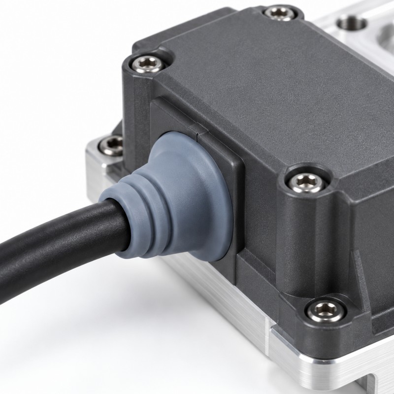
A silicone cable grommet or overmolded cable seal used near a liquid cooling system should protect the electrical feedthrough or cable exit without being confused with the primary coolant containment seal.
The sealing structure should be designed around the actual cable diameter, housing opening, assembly direction, cable jacket, silicone geometry, compression, strain-relief requirement, functional keep-out areas and environmental exposure.
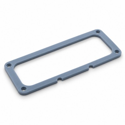
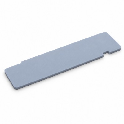
Where appropriate, a separate molded silicone grommet can be installed into the housing, or liquid silicone rubber can be molded directly around a cable, connector or plastic carrier to create an integrated sealing and strain-relief structure.
Final performance should be validated on the complete cable-and-housing assembly according to the customer's actual moisture, leakage, bending, pulling, temperature and electrical requirements.
Where Are Cable Grommets and Electrical Feedthrough Seals Used in Liquid Cooling Equipment?
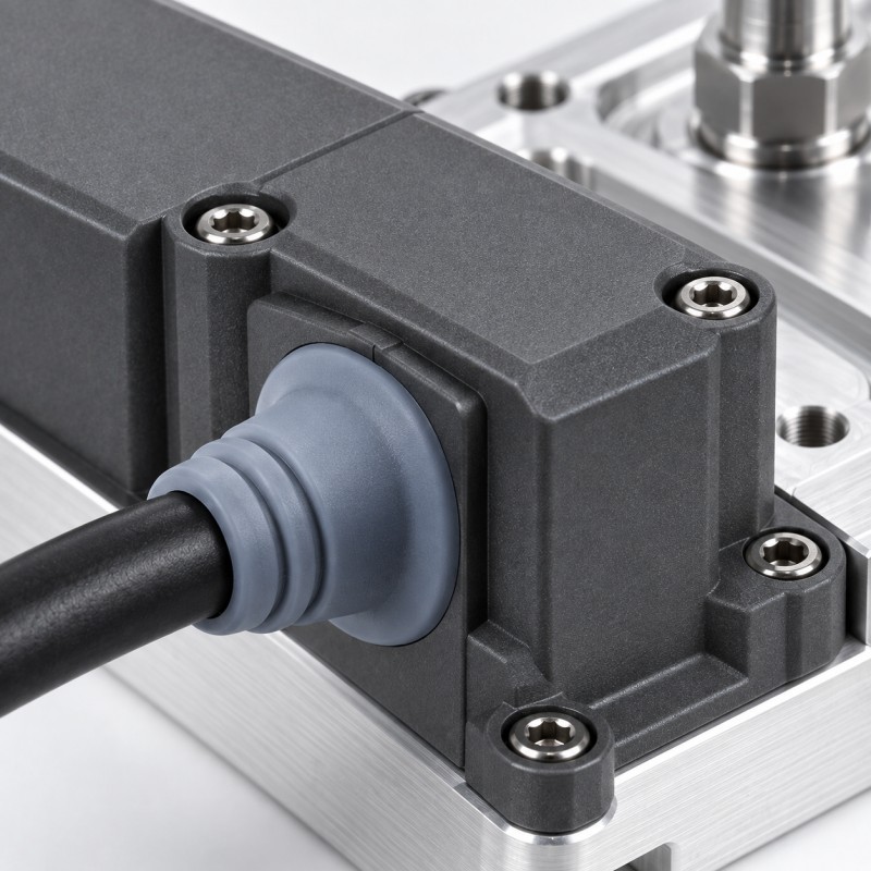
Liquid cooling equipment may place sensors, monitoring cables, power or control wiring and other electrical interfaces close to cold plates, manifolds, pumps, connectors or coolant-carrying components.
Depending on the equipment architecture, silicone sealing may be evaluated around:
• Sensor cable exits
• Electrical feedthrough openings
• Wire-harness passages
• Control cable entries
• Connector-to-cable transitions
• Plastic housing cable exits
• Metal-panel cable passages
• Monitoring-device wiring interfaces
• Other defined electrical entry points
These areas may need protection from external moisture, condensation, dust or unintended fluid exposure.
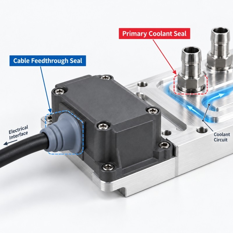
However, the cable grommet should not automatically be treated as the primary seal that contains the pressurized coolant circuit.
The primary coolant boundary and the electrical-interface protection boundary should be identified separately during DFM.
Why Is a Cable Exit a High-Risk Interface?
A cable exit combines a flexible cable with a relatively rigid housing or connector.
During assembly and service, this transition may experience:
• Bending
• Pulling
• Twisting
• Vibration
• Cable movement
• Housing movement
• Temperature changes
• Moisture exposure
• Condensation
• Accidental fluid exposure
If the transition is not controlled correctly, the cable may move relative to the seal or housing.
Possible results include:
• A gap around the cable jacket
• Seal displacement
• Local tearing
• Loss of compression
• Water or moisture ingress
• Cable-jacket damage
• Stress transferred to terminals or solder joints
• Overmold edge lifting
For this reason, sealing and strain relief should normally be reviewed together rather than as two unrelated features.
1. Separate the Coolant Seal From the Electrical Protection Seal
One of the most important design decisions is to define what the cable seal is actually expected to protect.
A liquid cooling assembly may contain several different boundaries:
• Internal coolant containment boundary
• Connector-to-manifold fluid seal
• Housing environmental seal
• Cable-entry seal
• Electrical insulation area
• Strain-relief zone
These functions should not be merged into one undefined silicone structure unless the complete design has been intentionally engineered for that purpose.
For example, if coolant is contained by a dedicated connector or manifold seal, the nearby cable grommet may only need to protect the electrical enclosure from moisture, condensation or secondary leak exposure.
This distinction helps engineers define the correct validation method for each sealing function.
2. Cable Diameter and Housing Opening Define the Seal Geometry
A cable grommet must match both the cable and the surrounding housing structure.
Important dimensions include:
• Cable outside diameter
• Cable diameter tolerance
• Housing-hole diameter
• Grommet inner sealing diameter
• Grommet outer locating geometry
• Panel or housing thickness
• Silicone sealing-lip dimensions
• Assembly direction
• Available deformation space
If the cable-side fit is too loose, a continuous sealing interface may not be maintained.
If the interference is excessive, assembly may become difficult and the cable jacket or silicone may be overstressed.
The housing side also needs enough structural support to prevent the grommet from shifting or being pushed through the opening.
For flexible silicone parts, the drawing should define critical functional dimensions together with a repeatable inspection method.
3. Cable Jacket Material Must Be Confirmed Before Overmolding
A cable is not simply a round insert with one universal surface condition.
Different cable assemblies may use different jacket materials, surface treatments, reinforcement layers and internal constructions.
Before LSR overmolding, engineers should confirm:
• Cable jacket material
• Cable outside diameter
• Surface texture
• Heat sensitivity
• Compression sensitivity
• Whether bonding is required
• Whether mechanical retention is available
• Required cable flexibility after molding
• Required electrical properties
Silicone adhesion should not be assumed only because the insert is described as a “cable.”
In some designs, the silicone structure may rely partly on geometric retention, wraparound coverage or connection to a rigid connector carrier rather than chemical bonding to the jacket alone.
The exact cable and connector samples should therefore be reviewed before tooling.
4. Strain Relief Should Reduce Stress Without Making the Cable Root Too Rigid
The purpose of strain relief is to spread bending and pulling loads over a controlled transition instead of concentrating them at one sharp cable root.
Useful structural considerations may include:
• Gradual silicone thickness transition
• Rounded geometry
• Controlled flexible length
• Smooth transition from rigid connector to cable
• Suitable silicone hardness
• Stable cable positioning
• Avoidance of sharp internal edges
A very short and rigid overmold may simply move the stress concentration to the point where the silicone ends.
A very soft or unsupported structure may allow too much cable movement and reduce sealing stability.
The correct design should balance cable movement, sealing and mechanical protection according to the actual bending and pulling requirement.
5. LSR Overmolding Requires Stable Cable Positioning
When a cable, connector or plastic carrier is placed inside an LSR mold, its position must remain stable during mold closing, injection, curing and demolding.
If the cable or insert moves, possible defects include:
• Uneven silicone thickness
• Off-center cable position
• Misaligned sealing ribs
• Exposed substrate
• Excessive flash
• Silicone entering a functional opening
• Unstable outer dimensions
• Different bending behavior between parts
Positioning becomes especially important when the cable itself is flexible and can bend or rotate before mold closing.
The mold or loading fixture should therefore use stable locating references wherever the component structure allows.
6. Electrical Contacts and Functional Openings Must Remain Silicone-Free
Cable and electrical interface parts often contain functional areas that cannot be covered by silicone.
Typical keep-out zones may include:
• Electrical terminals
• Connector contacts
• Test points
• Grounding surfaces
• Threaded holes
• Locating holes
• Connector mating faces
• Sensor windows
• Fluid ports
• Cable passages outside the defined overmold area
During LSR overmolding, liquid silicone can enter very small uncontrolled gaps.
The mold therefore needs a clearly defined shut-off boundary between the silicone area and each functional opening.
Even a thin silicone film on an electrical contact or mating surface can create an assembly or functional problem.
7. Separate Grommet or Integrated LSR Overmolded Cable Seal?
Both approaches can be suitable. The correct choice depends on the cable, housing and assembly process.
A separate silicone grommet may be appropriate when:
• The housing already contains a controlled mounting opening
• The cable must remain removable
• The seal needs to be replaced independently
• Final assembly can reliably position the grommet
• A standard cable routing process is preferred
An integrated LSR overmolded cable seal may be evaluated when:
• The silicone should remain permanently positioned on the cable or connector
• Manual grommet installation creates variation
• Sealing and strain relief should be integrated
• A rigid connector carrier can provide positioning support
• The geometry is suitable for insert molding
Overmolding can reduce separate components, but it also requires greater control of cable positioning, silicone coverage, mold shut-off and material interaction.
Design Item | Purpose | Main Risk | What to Review |
Protection boundary | Separates electrical area from exposure | Wrong seal function | Complete assembly |
Cable diameter | Controls cable-side seal | Gap or excessive interference | Cable tolerance |
Housing opening | Positions grommet | Seal movement | Hole and panel geometry |
| Jacket material | Defines insert behavior | Poor retention or deformation | Exact cable sample |
Strain relief | Reduces cable-root stress | Stress moved to overmold edge | Bend/pull requirement |
| Insert positioning | Controls silicone location | Off-center overmold | Mold fixture |
| Keep-out zone | Protects contacts and openings | Silicone contamination | Mold shut-off |
| Validation | Confirms final function | Sample looks good but fails in use | Assembly-level tests |
8. Thermal Cycling and Condensation Can Change the Interface
Liquid cooling equipment can operate through repeated startup, high-load and shutdown conditions.
Temperature changes may affect the cable, silicone, plastic housing and metal panel differently.
Possible long-term effects include:
• Change in seal compression
• Cable-jacket dimensional change
• Plastic housing movement
• Bonding-edge stress
• Silicone edge lifting
• Local cracking
• Moisture accumulation at an interface
• Reduced sealing consistency
Temperature variation can also contribute to condensation depending on the complete system and environment.
For critical electrical interfaces, the validation plan should therefore reflect the real operating conditions rather than only a room-temperature assembly check.
9. Electrical Insulation Requirements Must Be Defined by the Customer
Silicone can be used as part of an electrical protection structure, but the phrase “electrical insulation” is not a complete specification.
Depending on the project, engineers may need to define:
• Required insulating area
• Working voltage
• Test voltage if applicable
• Creepage or clearance requirements
• Required exposed contacts
• Material specification
• Silicone thickness
• Environmental conditions
• Validation method
The silicone should not cover an electrical contact that needs to remain functional simply because insulation is required nearby.
Likewise, no dielectric-strength or insulation-rating claim should be made until the selected silicone material and complete structure have been confirmed.
10. Coolant Exposure Should Be Treated as a Defined Condition, Not an Assumption
In many liquid cooling assemblies, the cable seal is outside the normal coolant containment path.
This means the cable grommet may normally see air, humidity or condensation rather than continuous coolant immersion.
However, some applications may require the component to tolerate accidental leakage, splash or direct fluid exposure.
If coolant exposure is part of the project requirement, engineers should define:
• Actual coolant type
• Concentration
• Exposure method
• Exposure duration
• Temperature
• Whether the cable jacket is also exposed
• Required post-exposure sealing or electrical test
Material compatibility should then be evaluated according to that specific condition.
Do not describe a cable seal as universally coolant-resistant unless the exact material combination has been validated.
How Should a Liquid Cooling Cable Feedthrough Seal Be Validated?
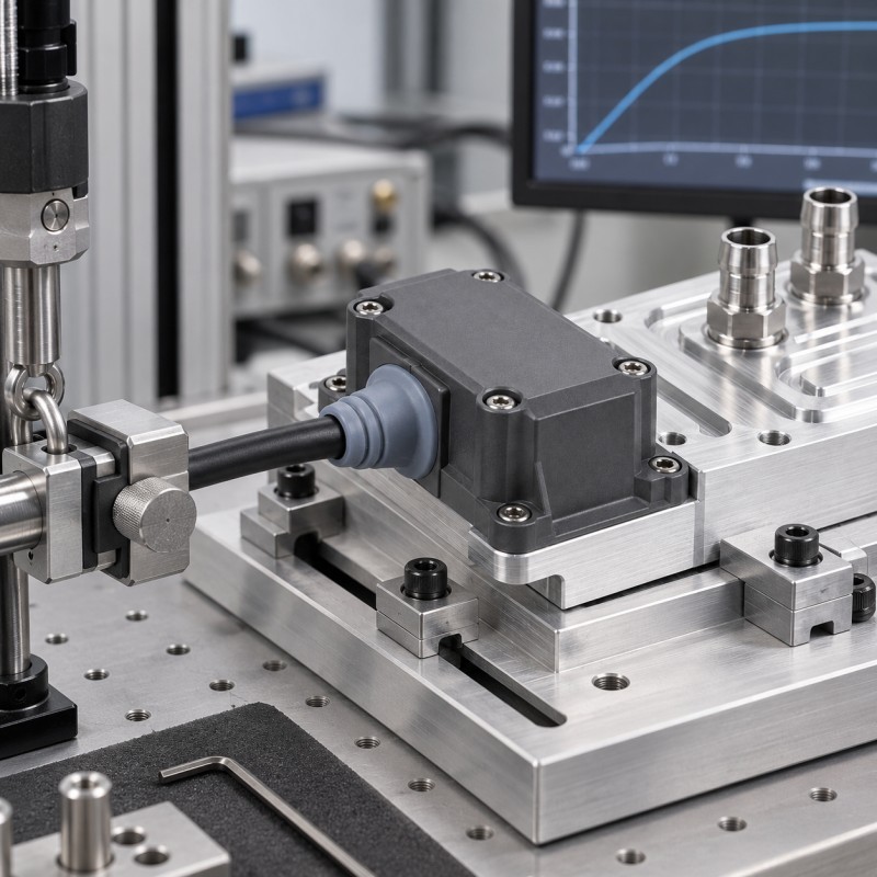
Validation should focus on the complete cable, seal and housing assembly rather than only the molded silicone appearance.
A project-specific validation plan may include:
1. Dimensional Inspection
Confirm cable position, silicone coverage, sealing dimensions, housing fit and functional clearances.
2. Assembly Check
Verify that the grommet or overmold installs correctly without twisting, pinching or interfering with adjacent components.
3. Cable Pull Evaluation
Confirm that the required pulling load does not cause unacceptable cable movement, seal displacement or interface damage.
4. Bending Evaluation
Check the cable-root transition according to the customer's defined bending method and acceptance requirement.
5. Environmental Sealing Test
Use the customer's defined moisture, water, air-leak or other environmental test when applicable.
6. Electrical Test
Where electrical insulation is a project requirement, use the customer's defined electrical validation method.
7. Thermal Cycling
Repeat functional inspection or sealing tests after the specified thermal exposure when required.
8. Fluid Exposure
If coolant contact is specified, evaluate the actual material combination under the defined coolant condition.
9. Pilot Production
Review multiple consecutive molded parts to confirm stable cable position, silicone coverage and functional performance.**
The objective is repeatable cable-interface protection in production—not one visually acceptable sample.
What Should Be Included in a Liquid Cooling Cable Seal RFQ?
For a more accurate DFM review and quotation, provide as much of the following information as possible:
• 2D drawing
• 3D assembly file
• Complete cable or wire-harness sample
• Cable outside diameter
• Cable jacket material
• Connector or carrier material
• Housing or panel opening dimensions
• Required silicone coverage area
• Areas that must remain silicone-free
• Sealing requirement
• Strain-relief requirement
• Bending requirement
• Pulling requirement
• Operating temperature
• Electrical insulation requirement if applicable
• Coolant exposure condition if applicable
• Environmental test requirement
• Estimated order quantity
For an overmolded design, the drawing should clearly identify where the silicone starts and stops and which electrical, mechanical or fluid interfaces must remain exposed.
Providing the physical cable sample together with the drawing can also help evaluate positioning, jacket condition and molding feasibility before tooling.
How SiliconePlus Supports Custom Cable Sealing and Overmolding Projects
SiliconePlus supports custom precision silicone molding and LSR overmolding for cable, connector, plastic, metal and electronic insert structures.
Engineering and manufacturing support can include:
• Drawing and DFM review
• Custom silicone grommet development
• LSR injection molding
• Silicone over plastic
• Silicone over metal
• Cable and insert positioning review
• Mold shut-off design
• Functional keep-out control
• Strain-relief structure review
• Silicone coverage review
• Flash-control evaluation
• Dimensional inspection
• Sample development
• Pilot production
• OEM/ODM mass production support
For liquid cooling equipment, the engineering review should first identify whether the requested component is a primary coolant seal, an electrical feedthrough seal, a cable strain-relief structure or a combination of defined functions.
Material and performance claims should then be confirmed according to the actual cable, substrate, environmental exposure and validation specification.
FAQ
What Is a Silicone Cable Grommet in a Liquid Cooling System?
It is a silicone sealing or protective component used around a cable, wire harness or electrical feedthrough. Depending on the assembly, it can help provide environmental sealing, cable positioning, insulation support and strain relief near liquid cooling equipment.
Should the Cable Grommet Be the Primary Coolant Seal?
Not automatically. In many systems, the pressurized coolant circuit has its own connector, manifold or cold-plate seal, while the cable grommet protects a separate electrical interface. The required function should be defined from the complete assembly.
Can Silicone Be Overmolded Directly Onto a Cable?
It can be molded around selected cable or connector areas when the cable material, geometry, heat sensitivity, positioning, required retention and molding conditions are suitable. The actual cable sample and jacket material should be reviewed before tooling.
Why Does a Cable Seal Also Need Strain Relief?
Cable movement, bending and pulling can disturb the sealing interface or concentrate stress at the cable root. A properly designed strain-relief transition helps manage these loads while maintaining the intended sealing structure.
Can an LSR Cable Seal Contact Coolant?
That depends on the exact silicone grade, cable jacket, coolant formulation, temperature and exposure condition. Compatibility should be validated for the actual material combination rather than assumed from the word “silicone.”
What Information Is Needed to Quote a Custom Cable Grommet or Overmolded Cable Seal?
Provide the drawing, cable sample, cable diameter, jacket material, housing structure, silicone coverage area, sealing requirement, bending and pulling requirements, operating conditions, test requirements and estimated quantity.
Conclusion
A liquid cooling cable grommet or electrical feedthrough seal should be designed around the real interface function rather than treated as a generic rubber sleeve.
A reliable design should coordinate:
• Primary versus secondary sealing boundaries
• Cable diameter and tolerance
• Housing geometry
• Cable jacket material
• Silicone geometry
• Strain relief
• Cable positioning
• Functional keep-out areas
• Thermal cycling
• Electrical requirements
• Fluid exposure conditions
• Assembly-level validation
A separate molded grommet can be appropriate for removable or conventional cable-entry structures, while LSR overmolding can be evaluated when sealing and strain relief need to remain accurately integrated with a cable, connector or rigid carrier.
The key is to define what the silicone must seal, what it must protect and which functional areas it must never cover before mold development begins.
Developing a Cable or Electrical Feedthrough Seal for Liquid Cooling Equipment?
If you are developing a custom cable grommet, electrical feedthrough seal, sensor cable interface or LSR overmolded cable component for liquid cooling equipment, send your 2D/3D drawings, cable sample, jacket material, housing structure, required sealing area, operating conditions and estimated quantity to the SiliconePlus engineering team.
Our team can review the cable positioning, silicone coverage, strain-relief geometry, mold shut-off, keep-out zones, dimensional requirements and manufacturing feasibility before tooling and sampling.
If coolant exposure or electrical insulation is part of the requirement, provide the actual fluid information and validation specification so the material and test requirements can be evaluated correctly.